0
\$\begingroup\$

Given is a STM32 G431 CBUx MCU and a TJA1051/3 CAN transciever.

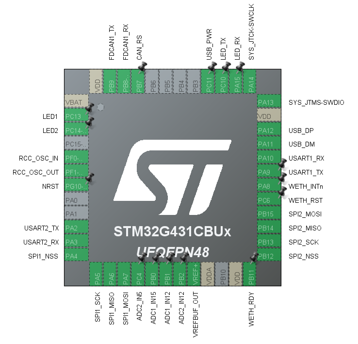
As I also need USB on this MCU, the only way to connect the CAN transceiver are pins PB8 (FDCAN1_Rx) and PB9 (FDCAN1_Tx). The problem with that is: PB8 is also the Boot0 Pin. At power up the transceiver is in sleep mode, pulling the pin to HIGH.

MCU pinout

I could solve this through the option bits. But I'd prefer a hardware solution. I use PB7 as control pin for the "S" (sleep, active low) input pin of the CAN transceiver, which is hardwired (via a 10k resistor) to Vcc and pulled down by a 2N7002 (Gate <---> PB7), I could also use this pin to make sure the Boot0 Pin is pulled to GND during power-up.

If I only take the functionality into consideration, a mini SPDT relay would do the job. Or I could use an AND-gate. The benefit of the relay would be: I could connect the NC pin to a push-button or a jumper and use the Boot0 Pin of the MCU in standard configuration without chaining the option bytes. But I do not recall considering that as a "sophisticated solution", rather I'd see that as inappropriate...

What I'd need would be some kind of IC that is able to switch the signal path according to an input pin. Could an analog channel multiplexer be a solution? What about the signal delay in such circuits? Has someone an idea and can point me in the right direction?

\$\endgroup\$
2
  • \$\begingroup\$ I found this chip: Texas Instruments TS5A3159A ti.com/product/TS5A3159A . But I have no idea, how it behaves with digital circuits. Has anyone ever used this chip in digital circuitry before? \$\endgroup\$
    – pm4812
    Commented Sep 2, 2023 at 8:53
  • \$\begingroup\$ I guess i will try it with my actual setup and an Texas Instruments SN74LVC1G315. This IC is speced for I2C/SPI/UART bus multiplexing, which goes in the right direction \$\endgroup\$
    – pm4812
    Commented Sep 2, 2023 at 9:33

1 Answer 1

1
\$\begingroup\$

You can just set the CAN trasceiver into a mode where it does not drive the RXD input until MCU boots and changes the CAN transceiver to enable the RXD output.

EDIT: OK so this CAN chip version does not have EN pin so RXD can't be tristated.

Use a three state buffer between CAN RXD out and MCU CANRX input.

Set the buffer enable state with a resitor to be disabled by defauly. Then you can define the BOOT0 pin state as you wish with pull-up or pull-down resistors and pushbuttons or jumpers to go into bootloader mode.

Then in your main program, use an IO pin to enable the three state buffer when ready.

It could have been easier to use a CAN chip with output enable pin built-in.

The STM32 CAN pins are 5V tolerant so you could use a 5V chip, except that this particular chip does not work with 3.3V IO, but some other CAN chip might accept 3.3V as valid high input level.

Sure an analog mux could do as well, but the thing with logic level buffers, tristateable or not, can be used to convert between 5V and 3.3V logic levels. The analog mux can't do that, but in this case, you don't need it to.

Otherwise an analog mux or an analog switch could be used just fine to disconnect the CAN chip RXD output from MCU CANRX input.

\$\endgroup\$
4
  • \$\begingroup\$ this specific transciever does not have this option. It only has a "sleep" mode, but not an "enable/disable" Pin. The TJA1051T/E would have an enable pin, but that IC is for 5 Volt MCUs, not 3V3 ... \$\endgroup\$
    – pm4812
    Commented Sep 2, 2023 at 8:38
  • \$\begingroup\$ @pm4812 Ah sorry I did not realize that it does not have EN pin. But the MCU CAN pins are 5V tolerant so you could use a 5V CAN chip. Except that this 5V CAN chip cannot work with 3.3V on inputs unfortunately. But I can still suggest a solution. \$\endgroup\$
    – Justme
    Commented Sep 2, 2023 at 8:52
  • \$\begingroup\$ no prob. Yes. selecting a differenct CAN IC woulde be an alternative, for sure. ATM I'd like to stick with this particular IC, because I know it well and had no issues with that IC so far in similar configurations (with an STM32). In my comment under the initial posting. I have mentioned an anlog multiplexer IC. But I have no idea how these devices perform in logic circuits. Have you eventually some experience with that? \$\endgroup\$
    – pm4812
    Commented Sep 2, 2023 at 9:00
  • \$\begingroup\$ thanks for pointing me in the right direction! \$\endgroup\$
    – pm4812
    Commented Sep 2, 2023 at 9:09

Your Answer

By clicking “Post Your Answer”, you agree to our terms of service and acknowledge you have read our privacy policy.

Not the answer you're looking for? Browse other questions tagged or ask your own question.