0
\$\begingroup\$

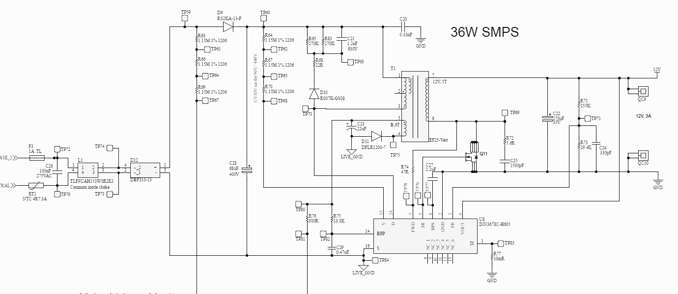
I'm encountering a design issue with my switch-mode power supply that utilizes the InnoSwitch3-EP (INN3678C). The SMPS powers up and outputs the required V when the input voltage is 133VAC or higher, under full load conditions (drawing 3A), but I'm facing problems when trying to achieve reliable operation within a lower input voltage range of 85VAC to 110VAC at full load.

When I change the input to a lower voltage e.g 100VAC it does not power up. I can hear clicking noises from the SMPS, maybe stuck in auto reset mode ?

Things I have tried.

  1. Tried different combination of undervoltage sense resistor, still no result the minimum stayed around 130VAC.
  2. Shorted the undervoltage pin to source so it disables it, as per datasheet. The minimum input AC at full load was 150VAC.
  3. Measured across C23 on the primary bias and I can see it was oscillating until the input AC reached ~130VAC. Then it was 15V.

enter image description here

The power supply was designed with universal input (85V-240V). Any help on what I should try doing next?

\$\endgroup\$
6
  • 2
    \$\begingroup\$ How was the transformer designed? Is it proven in this circuit for operation from 85 V - 264 V? \$\endgroup\$
    – John D
    Commented Sep 12, 2023 at 23:38
  • \$\begingroup\$ I obtained the transformer by purchasing it from an online vendor who took care of building it for us. The circuit was created using PI Expert, which provided us with all the necessary details and guidance, which shared these instructions with the vendor. Just a question, when power is applied, does the SMPS immediately output the required 12V, or is there a delay of a few seconds? \$\endgroup\$
    – S_D
    Commented Sep 12, 2023 at 23:51
  • 3
    \$\begingroup\$ The controller has a soft-start, but the output shouldn't take several seconds to come up, I think it should be well under a second. I suspect a transformer issue, maybe with the aux winding. Could be too much leakage inductance, or not enough turns but those are just guesses. \$\endgroup\$
    – John D
    Commented Sep 13, 2023 at 0:03
  • 1
    \$\begingroup\$ You design a power converter based on the valley voltage of the bulk cap. where it has to deliver full power at the lowest \$V_{ac}\$. I believe 68 µF should be enough but you may want to power your converter with a dc input voltage and start it with a sufficiently-high value so that it delivers the nominal power. Then, slowly decrease the dc input until the power supply gives up and protect itself. It could be the peak current limit that is set too low, the transformer starting to saturate or the timer duration that is too short and the output cap. too large to charge within the timer range. \$\endgroup\$ Commented Sep 13, 2023 at 11:40
  • 1
    \$\begingroup\$ Also, why did you insert another diode after the diode bridge: a) it hurts efficiency and b) any side effect with brown-in/out sensing of the PI part? The sense network works with current injected in the pin. You may want to short this diode for experiment purposes and see if it affects operations or not. \$\endgroup\$ Commented Sep 13, 2023 at 11:44

1 Answer 1

0
\$\begingroup\$

Re-designed SMPS with a new transformer and it worked as per.

\$\endgroup\$
2
  • 1
    \$\begingroup\$ Could you expand a little bit on what was re-designed? \$\endgroup\$ Commented Mar 8 at 1:13
  • \$\begingroup\$ Absolutely! I substituted the E25/13/7 (EF25) with the PQ20/20 core/bobbin and opted for a different MOSFET. Everything else in the circuit remained essentially similar. This adjustment was made using the PI Expert Suite. Tested the SMPS and it was working as I wanted. \$\endgroup\$
    – S_D
    Commented Mar 8 at 1:49

Your Answer

By clicking “Post Your Answer”, you agree to our terms of service and acknowledge you have read our privacy policy.

Not the answer you're looking for? Browse other questions tagged or ask your own question.