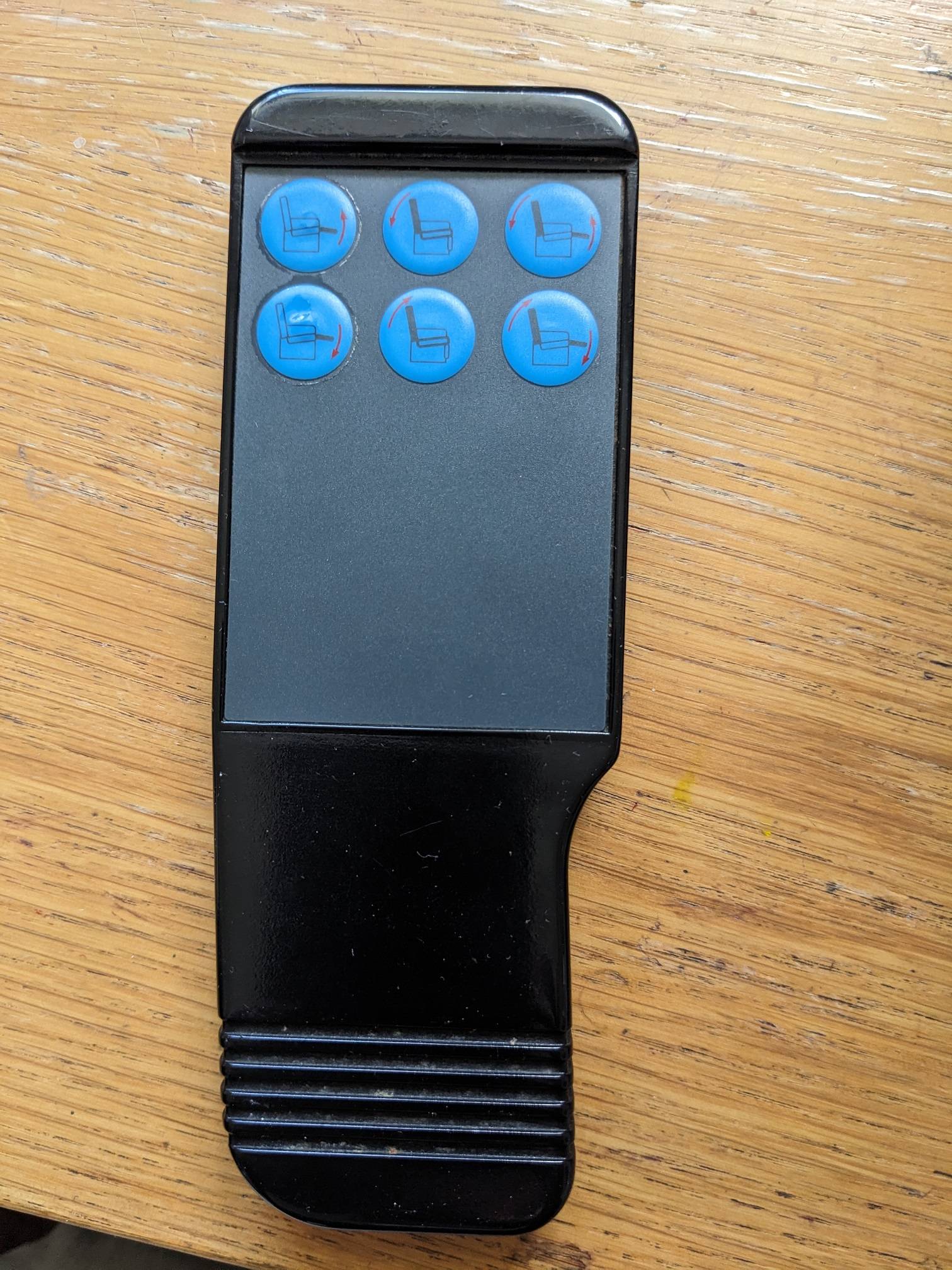
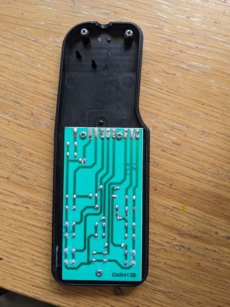
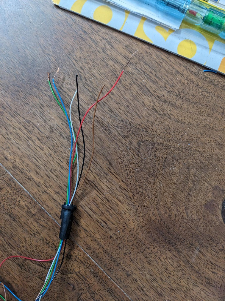
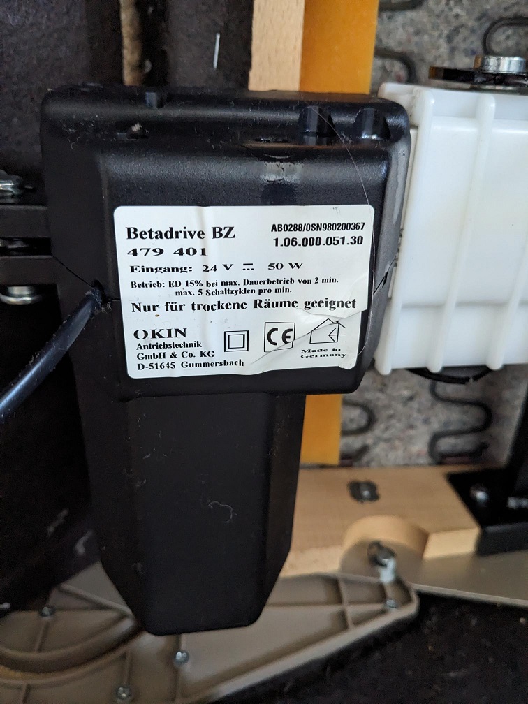
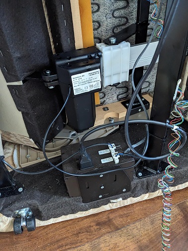
I feel this is a really long shot but the reclining chair of my father has broken. I am trying to help fix it. The remote is no longer able to make the chair's motor operate and pull the back of the chair into the upright position - currently its horizontal which is a nightmare. The wires have come away from the remote control and I would like to try and solder then back but I don't know which cable goes to which contact. So any help here would be great. Alternatively I would be happy if there was a way in which I could disengage the motorised armature and manually adjust the back to be in an upright position. I've attached some pictures to give you an idea. The ID on the circuit board is CIAR413B.
-
\$\begingroup\$ Hi Robbie, I'm afraid repair questions are off-topic here. But even if they weren't, it's just as impossible for us as for you to guess the function of each cable. \$\endgroup\$– Marcus MüllerCommented Oct 31, 2023 at 14:46
-
\$\begingroup\$ I was hoping that someone might be familiar with that circuit and know the correct configuration or could supply the circuit diagram. \$\endgroup\$– robbie70Commented Oct 31, 2023 at 15:02
-
\$\begingroup\$ again, many beginners hope that, and it's a) almost never the case (count the thousands upon thousands of electronic consumer devices around you: what are the chances that a small group of people has schematics to any specific one???) and it's also b) decidedly not what such a question & answer platform like this should be used for. This is not a schematic database with a human query interface; it's a platform where experts answer technical questions. That's exactly why we put requests like that off-topic. \$\endgroup\$– Marcus MüllerCommented Oct 31, 2023 at 15:08
1 Answer
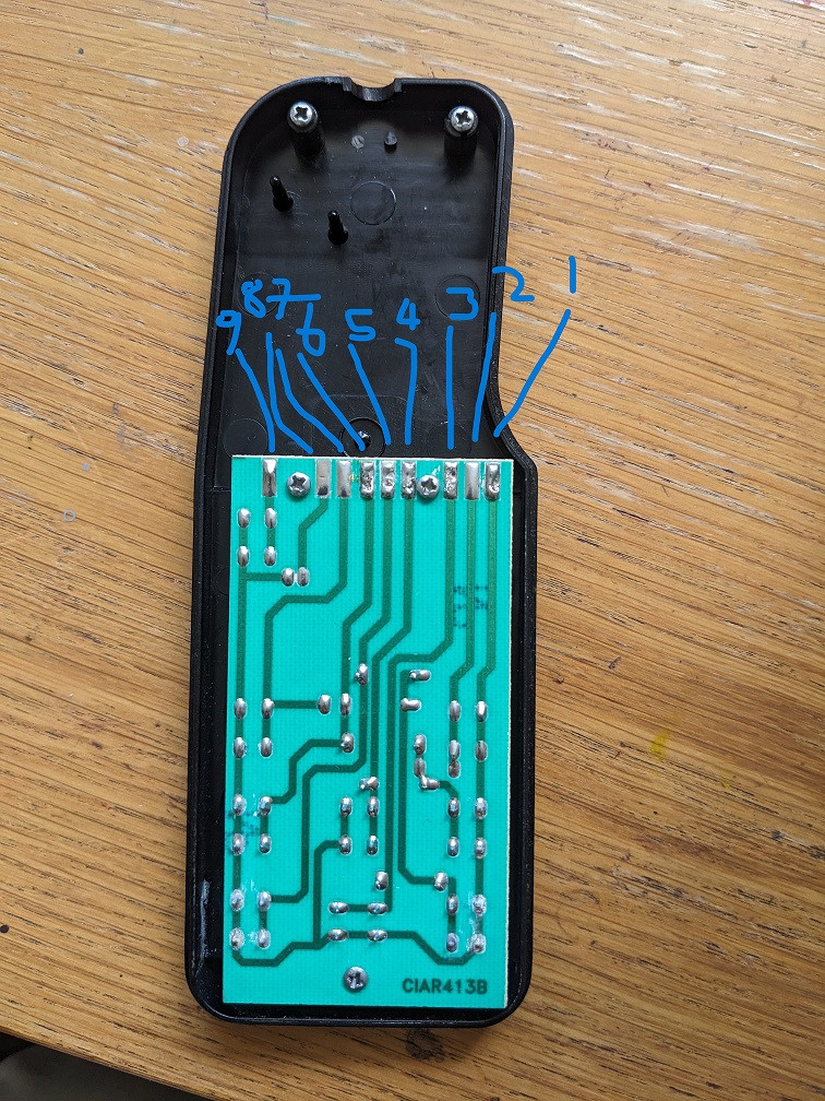
What you need to do is try touching different wires to each other to see if they complete the circuit and move the motors. I would assume that the black wire is the common wire, so try touching the other wires to the black wire, but DO BE CAREFUL because the wires might carry high voltages, but unlikely; I would need a better look at the circuitry where the wires connect to the chair. When you find which wire is the common wire, solder this wire to pin 1 in your photo. The common wire is the one wire that needs to touch other wires to move the chair. The other four wires need to be soldered to the other pins. How you find out which wires go where is relatively easy:
If you find, for example, that the brown wire moves the footrest down when connected to the common wire, follow the trace from the button under the "footrest down" button to pin 5. Solder the brown wire here. Each button has 2 traces from it. One trace goes to pin 1 and the other to a different pin. Follow this method for the rest of the wires.
There is one exception: From what I understand, each wire moves one footrest/backrest on only one direction. According to this, there should only be 4 other wires, so one of the wires will be different. It appears it should connect to pin 9, but it doesn't look like it does anything, and I think it would be safe to cut it off... :P
Notes:
Not all the pins will have a wire because these are for extended features that your chair does not have.
The buttons that move both footrest and backrest are connected to their respective footrest and backrest buttons, and don't need wires.
Hope this makes sense!
-
\$\begingroup\$ That's a great answer @Klumpy . You won't believe it but after posting the question I soldered the red blue and green cables onto the contacts as my mother thought she remembered those. It had no effect. Then I just started playing around and did exactly what you suggested and used the black cable to touch on the contacts to see if I could hear anything. As I touched the contacts I could hear something and then when I touched the first pin the back started moving vertically again ! With your tips I will try and fix it properly. Thank you. \$\endgroup\$– robbie70Commented Oct 31, 2023 at 15:14
-
1\$\begingroup\$ Attention if you reverse the 0V (or ground) and the power (24V?) on the board or put them where it's wrong you risk destroying the circuitry. The black wire is likely 0V-ground and the red wire the power (24V or less). Measure the voltage between black and red. Your first attempt didn't work because you didn't connect the ground (black). But you vonnected the red. It's possible that when a button is pressed, the signal goes from high (some voltage) to low (0V) or the opposite. So don;t be surprised if the button sinks current to ground. Showing the other side of the board could help. \$\endgroup\$– FredledCommented Oct 31, 2023 at 16:26
-
1\$\begingroup\$ If there were high voltage on one of these wire (which is not 100% excluded) then the CE mark on the device would be a fraud. LOL. \$\endgroup\$– FredledCommented Oct 31, 2023 at 16:28
-
\$\begingroup\$ Thanks @Fredled for the tips. I dont know exactly how it worked. I soldered the red cable onto the 1-pin, the blue onto the 3-pin and the green onto the 5-pin because my mother thought thats what she remembered and I didnt have any better ideas. I then touched the black cable onto the 1-pin (while the red cable was soldered there and it seemed to work !). The chair is in a dormant state - unplugged. If I get a chance I will unscrew the circuit board and take a picture and add it to the post. And I may try and fix it properly to get the remote working again. Thanks for your comments. \$\endgroup\$– robbie70Commented Oct 31, 2023 at 17:43

