0

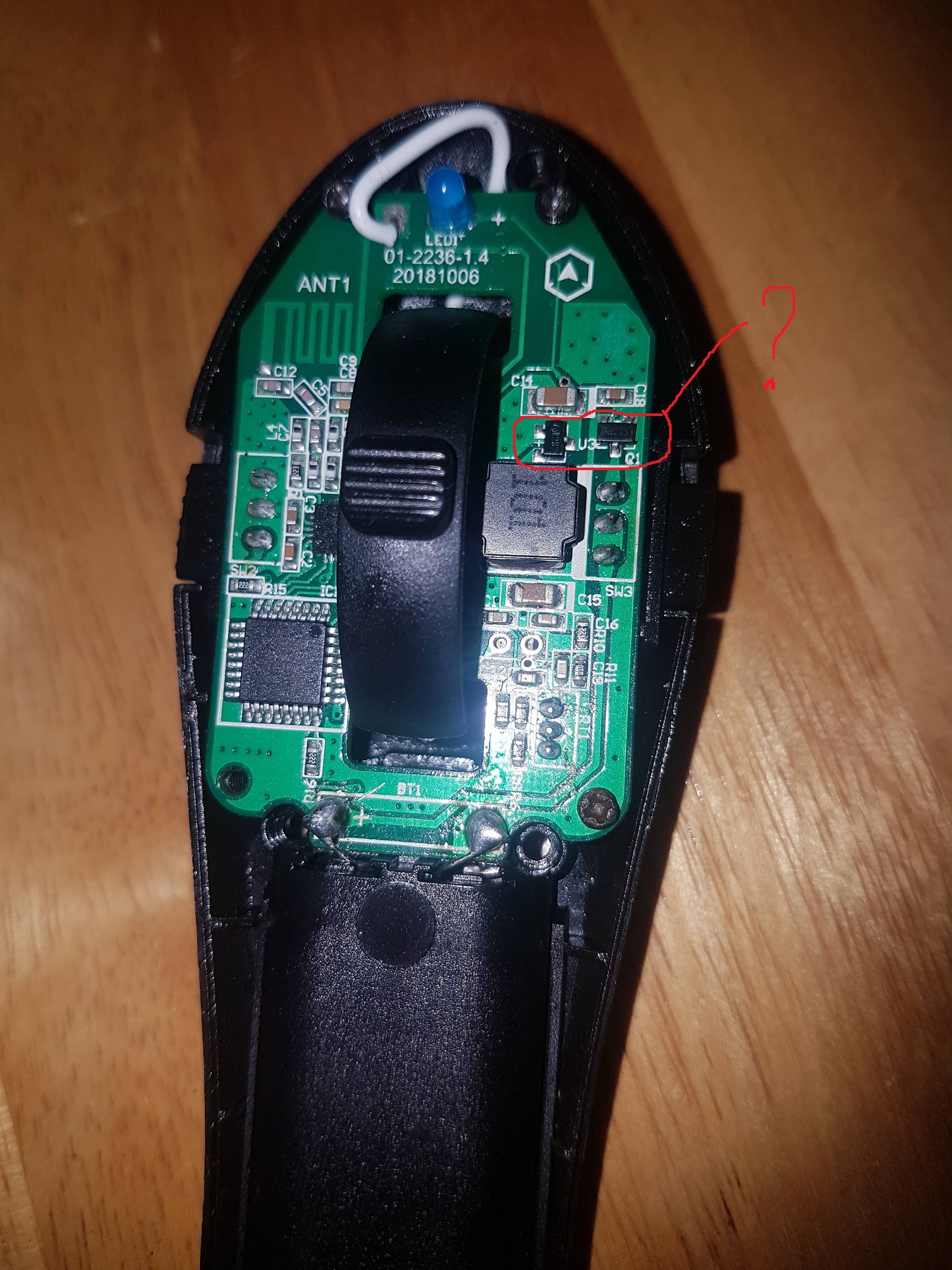
The picture below is the PCB of a Xiaomi Acton Electric Skateboard Remote Control.

Basically it is a 2.4 GHz transmitter, transmitting the value of a potentiometer (throttle). Normally when the switch is ON the blue LED will blink.

The remote controller suddenly stopped working, the LED wasn't blinking anymore, and I found out the 2 ICs circled RED in the picture below are way too hot, probably broken.

I don't know what those two ICs are. The IC on the right (labeled Q1) seems like a voltage regulator but I'm not sure. There is a printed label on top of the IC ("Al2RD"). The "Al" looks like a logo. The IC on the left (labeled U3) is labelled "X7DP88". I couldn't find those texts in an online search.

The remote control is powered by 2xAAA 1.5 V batteries yielding ~3 V at Vbat.

Could you help me find out what those ICs are? Or at least what their function is (i.e voltage regulator, diode, transistor)?

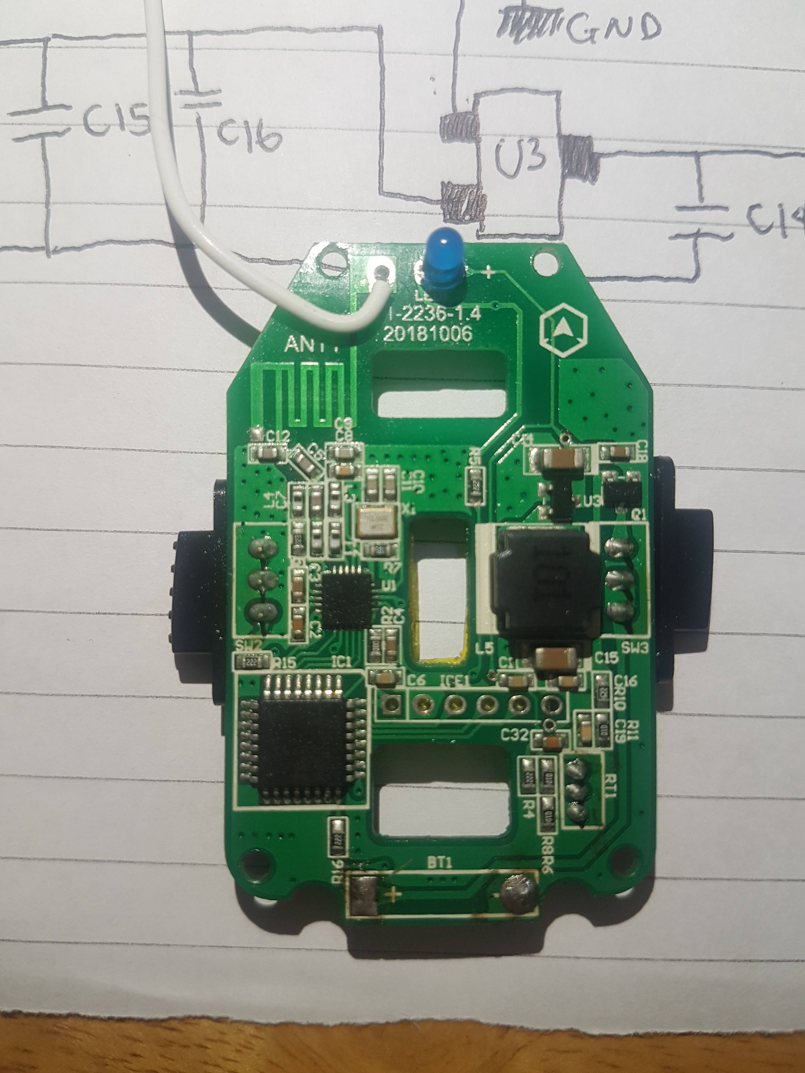
PCB1

PCB2

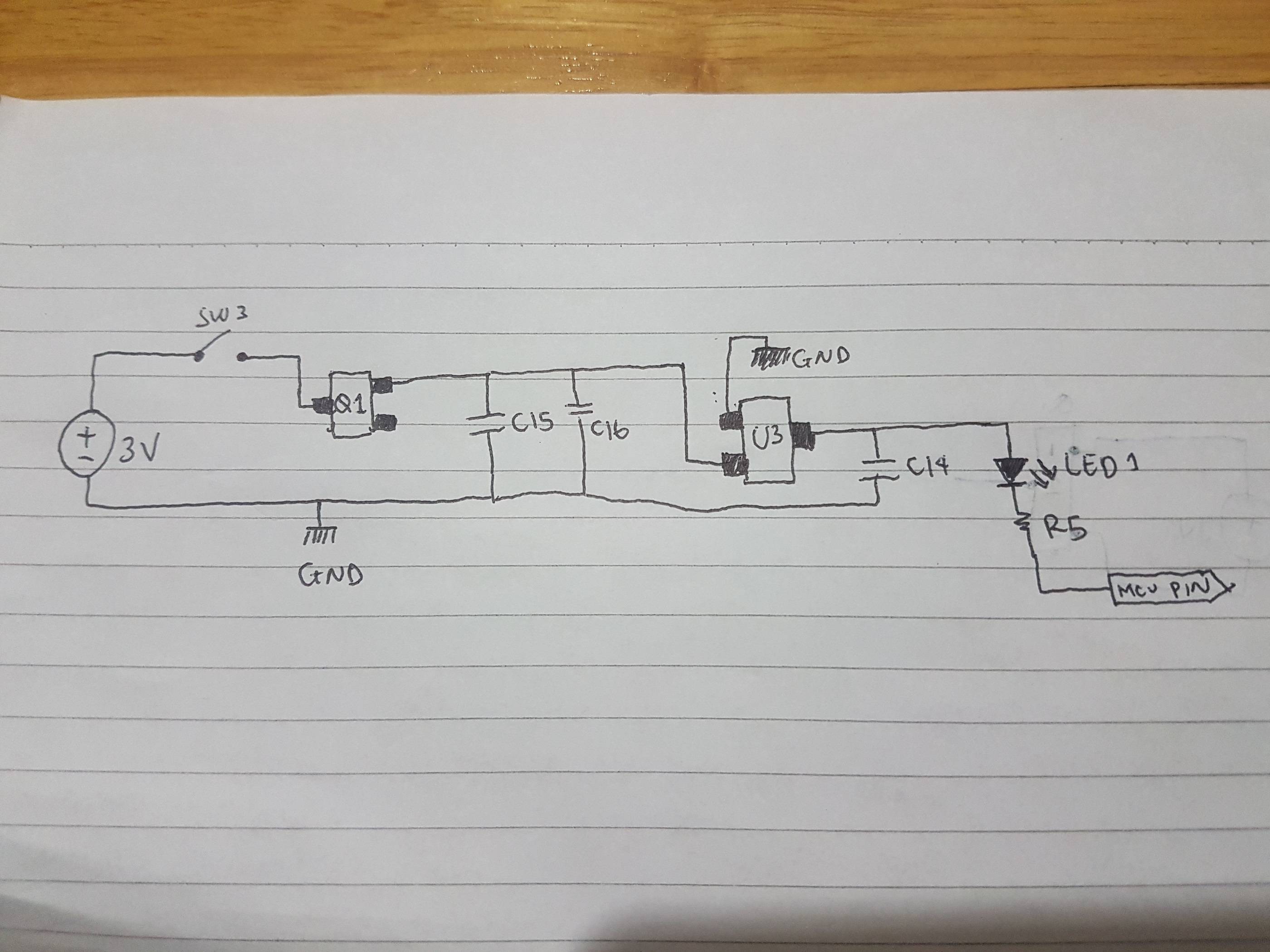
Update A quick connectivity test with a multimeter, I came to the schematic below :

Schematic

It seems like Q1 is some kind of regulator. If it is, then to what voltage doed it regulate the 3 V battery? I thought the logic level of most MCU was 3.3 V. Now what if I use a super new 3 V battery? Could I just bypass this regulator, just to verify if it will turned ON?

The U3 seems like an LED controller (to make it blink?). Is it?

4
  • First step would be to use a multimeter and trace out the schematic. Q1 is most likely a FET or transistor, while U3 is some sort of IC (following common reference designator nomenclature). If you can provide a schematic it'll be much easier to determine what they are.
    – Stiddily
    Commented Feb 25, 2020 at 13:03
  • Is it still possible to read the writing on Q1 and U3? I suspect that U3 may be a LDO voltage regulator.
    – Simon B
    Commented Feb 25, 2020 at 13:25
  • Welcome to EE.SE! This appears to be a reverse engineering, modification, or repair question. Please be aware that such questions must involve specific troubleshooting steps and demonstrate a good understanding of the underlying design of the device being discussed, so that you can ask specific, focused questions that can be answered concisely. Otherwise, the question is far too broad. More information can be found here: Is asking how to fix a faulty circuit on topic?.
    – Dave Tweed
    Commented Feb 25, 2020 at 14:24
  • 1
    Hi all, thanks for the reply. I updated the question with a schematic of the PCB I aquired by a connectivity test from a multimeter.
    – erichps
    Commented Feb 25, 2020 at 16:51

1 Answer 1

1

Sounds like they could be either LDO, Transistors, MosFETS or diodes. To identify them you'll need a digital multi-meter and I would follow this simple method:

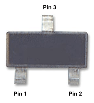
SOT23-3 pin number identification

  1. Disconnect batteries, Use diode mode to check between Pin 1 and Pin 2 (and reverse)

If it appears to read around 0.7V in one direction then it's likely a transistor, else carry-on.

  1. Use diode mode to check between Pin 1 and Pin 3

If it appears to read around 0.7V then it's likely a diode, else carry-on.

  1. Reconnect the batteries. Measure voltage Vg between Pin 1 and Pin 2

If absolute Vg voltage value is greater than ~2V and voltage on Pin 2 is similar to voltage on Pin 3 then it's most likely a MosFET. If voltage Vg is close to 0V and Pin 3 and Pin 2 voltage values are different, it is also likely a MosFET. Else carry-on.

  1. Read voltage between Pin 1 and Pin 3 (V1), between Pin 2 and Pin 3 (V2)

Is voltage V1 inferior to V2? Then it's most likely an LDO.

EDIT

To be clear, this method would only work if U3 and Q1 are still indeed functioning. If you can't determine what is what, it probably indicates malfunctioning packages. In that case, you may want to reverse engineer the circuit around them to figure out their function.

3
  • 2
    But that rather assumes that U3 and Q1 actually work. If they are fried, it's anyone's guess what the measurements will be. And if they aren't fried, they don't need replacing anyway.
    – Simon B
    Commented Feb 25, 2020 at 13:24
  • @SimonB Good catch, edited my post. Thanks!
    – eeintech
    Commented Feb 25, 2020 at 14:38
  • @Cisco25 I have checked the Q1, none of the combination of PIN showed 0.7 V reading on diode test. I have updated the question to include a schematic I aquire from connectivity test the PCB.
    – erichps
    Commented Feb 25, 2020 at 16:53

Your Answer

By clicking “Post Your Answer”, you agree to our terms of service and acknowledge you have read our privacy policy.

Not the answer you're looking for? Browse other questions tagged or ask your own question.