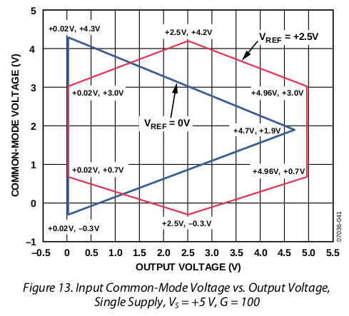
What are limitations on the design imposed by this graph? Say, if I want my output to span 0V - 3.3V, does this mean that I should position my input signal at 2.5V?

edit: InAmp in question is AD8226
What are limitations on the design imposed by this graph? Say, if I want my output to span 0V - 3.3V, does this mean that I should position my input signal at 2.5V?

edit: InAmp in question is AD8226
That graph is effectively 3D. It shows:
It shows that if all you want is the output to swing from 0-3.3V, there are an infinite set of combinations that will work.
It shows that Vref could be anything (all values of Vref between 0 and Vs) include at least one value of the common-mode voltage where 0-3.3V is included
That's not really useful because in real-life, you have some additional constraints on the input.
What is the common-mode voltage of your input?
Is your signal bi-polar (swings above and below common-mode voltage) or differential?
Are you referencing the signals to each other or a third reference?
Etc...
As indicated, the INA is powered with a unipolar 5VDC source (0V and 5V negative and positive rails respectively)
If you have a ground-referenced unipolar sensor, the input voltage of the sensor might be 0V to 100mV (for example).
This will cause you problems because the output range of the INA when faced with a common-mode voltage of 0 cannot reach 3.3V independent of any possible Vref setting.
You will need to raise the common-mode voltage of the sensor to at least ~1.5V
You then set the INA gain to 33X and Vref to 0.