3
\$\begingroup\$

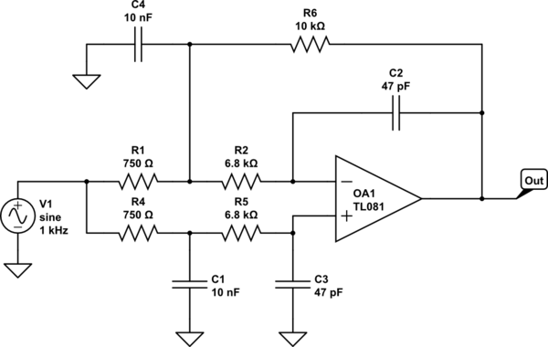
While experimenting with various low-pass filter topologies (audio application), I came up with the following design:

schematic

simulate this circuit – Schematic created using CircuitLab

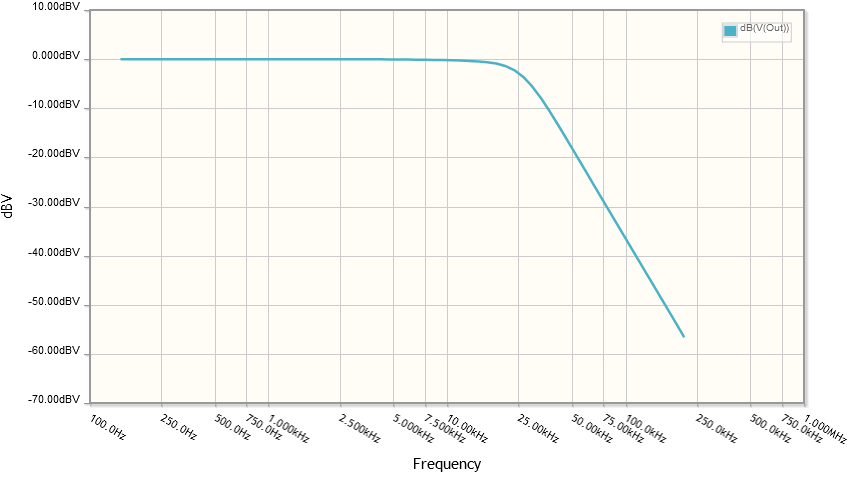
It seems to produce -18dB/octave response, so it must be a 3rd order filter.

Frequency diagram

This circuit does not invert phase. Why does it work like that? Is this a practical filter configuration?

\$\endgroup\$
1
  • \$\begingroup\$ bkxp, It's technically 4th order. But with the risk of missing something important, you can imagine that R4+C1+R5+C3 form a 2nd order LP to the (+) input. This must be reflected at the (-) input. So there's the same 2nd order LP at the (-) input (ideally.) This must be integrated by C2 to form Vout, because vin*(LP 2nd order)=vout*s*C2, or vout/vin=(LP 2nd order)/(s*C2). That's 3rd order behavior. (Granted R6+C4 forms a 1st order LP of vout into the node joining R1+R2. But it's ignorable here because vout is still the integral of a 2nd order LP.) Can't be inverted. \$\endgroup\$ Commented Nov 16, 2023 at 4:00

2 Answers 2

2
\$\begingroup\$

Is this a practical filter configuration?

A standard 3rd order filter with a gain of unity that uses an op-amp would use 3 resistors and 3 capacitors. Your circuit uses 5 resistors and 4 capacitors. This makes it less practical than the standard solution.

Maybe if you can show it has some advantage over a standard Sallen-key op-amp filter it's worth pursuing.

This circuit does not invert phase. Why does it work like that?

It doesn't invert phase because there is more circuit gain in the non-inverting path than there is in the inverting path (due to R6) but, as frequency passes the cut-off point, R6 becomes gradually less dominant with respect to the lowering impedances of C4 and C2 and, can be ignored.

This then leaves two gain paths (one inverting and one non-inverting) that gradually becomes closure in magnitude and eventually become equal in magnitude at very high frequencies thus, overall circuit gain falls to zero (absolute terms).
\$\endgroup\$
2
  • \$\begingroup\$ But how exactly does this circuit become a 3rd order filter, Considering that the inverting part of it is similar to 2nd order MFB topology, and the non-inverting part is also a 2nd order filter (yet close to 1st order in the audio range). And the symmetry is important here to get a normal flat curve with a slope. \$\endgroup\$
    – bkxp
    Commented Nov 15, 2023 at 16:02
  • \$\begingroup\$ That's not true what you said about the non-inverting part. Did you get my comment on your other question? \$\endgroup\$
    – Andy aka
    Commented Nov 15, 2023 at 21:11
0
\$\begingroup\$

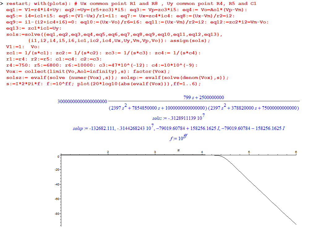
Here is a Maple resolution of the circuit.

You can see that fundamentally, it is a "4th" order filter.
However, one can note that the zero and one pole are approximately at the some place.
So, it is "really" a 3rd order filter.

enter image description here

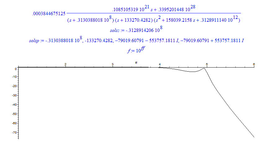
Here is the result when c3 & c2 are only 4.7 pF.

enter image description here

\$\endgroup\$
2
  • \$\begingroup\$ Thanks for providing this comprehensive analysis! Now I see why this behaves like a 3rd order filter. Do you have any insight about why the pole and the zero are approximately the same for this circuit? \$\endgroup\$
    – bkxp
    Commented Nov 16, 2023 at 15:54
  • \$\begingroup\$ For what "parts" of the circuit contribute to the poles and zero, FACTs analysis may be done. I am not "able" to do that. Just ask to @Verbal Kint . He is the right man. \$\endgroup\$
    – Antonio51
    Commented Nov 16, 2023 at 16:01

Your Answer

By clicking “Post Your Answer”, you agree to our terms of service and acknowledge you have read our privacy policy.

Not the answer you're looking for? Browse other questions tagged or ask your own question.