8
\$\begingroup\$

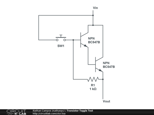
I'm trying to learn about how transistors work. As a simple test I created the following circuit:

Toggle Circuit

My idea is that when the second transistor will keep the first one active after I click the button for the first time, but it isn't. What am I doing wrong?

\$\endgroup\$
1
  • 2
    \$\begingroup\$ FYI that transistor combination you came up with is called a darlington pair. Since you're interested, look it up. \$\endgroup\$ Commented May 12, 2013 at 16:35

3 Answers 3

5
\$\begingroup\$

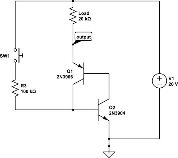
What you are trying to create is a thyristor and it is slightly different.

schematic

simulate this circuit – Schematic created using CircuitLab

To sustain a transistor on you need current through the gate, in this design the two transistors are feeding output through each other.

\$\endgroup\$
4
  • \$\begingroup\$ Thanks very much for your help, the circuit is working perfectly! Also, I was playing around with it and if I put a button to short the base of the PNP to ground (or the base of the NPN to Vin) I can turn the output off. \$\endgroup\$ Commented May 12, 2013 at 16:30
  • 1
    \$\begingroup\$ The circuit as shown is not a suitable design. The base current that the PNP is expected to pass will be well over 450 mA. Same thing for the NPN. The total current through the load would be over 900mA. Both these numbers are well over the nominal ratings for the components shown. As a matter of fact the maximum sustained current on the base of a small signal transistor like these should not be more than a small number of mA. The maximum collector current of either device should be limited to less than 200mA. \$\endgroup\$ Commented May 12, 2013 at 16:59
  • \$\begingroup\$ @Kortuk - The original posters schematic does not show the load so we cannot determine if the powersupply is shunted or not. When showing what you did in your posting you are doing a disservice to the engineering community as shown because many could come here and believe it to be the way to go because the poster gave you the green check mark. Please at least change the component values in your diagram to a realistic set of values. \$\endgroup\$ Commented May 12, 2013 at 20:14
  • 1
    \$\begingroup\$ @MichaelKaras I would note, I was attempting to explain what he was making here, which he should really be buying an SCR for, not putting two transistor back to back for a poor approximation. \$\endgroup\$
    – Kortuk
    Commented May 12, 2013 at 22:06
3
\$\begingroup\$

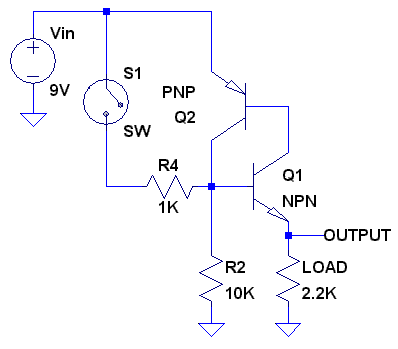
You will need a somewhat different circuit configuration to achieve a hold on latch. A couple of transistors interconnected like shown here would do the trick.
enter image description here

Note that with this configuration the maximum safe load current cannot exceed the maximum steady state current that the PNP transistor can sustain. For small signal transistors such as the 2N3904 and 2N3906 this limit will be on the order of about 5mA. So if you want to use this to switch a higher current load you would want to connect another switching circuit to the output of this latch.
\$\endgroup\$
0
\$\begingroup\$

After you release the button, there is no path for current to enter the base of the top transistor. For the transistors to stay on, the base of the top transistor must be about 1.2V above Vout but your resistor will pull the base of the top transistor down to Vout.

\$\endgroup\$

Not the answer you're looking for? Browse other questions tagged or ask your own question.