1
\$\begingroup\$

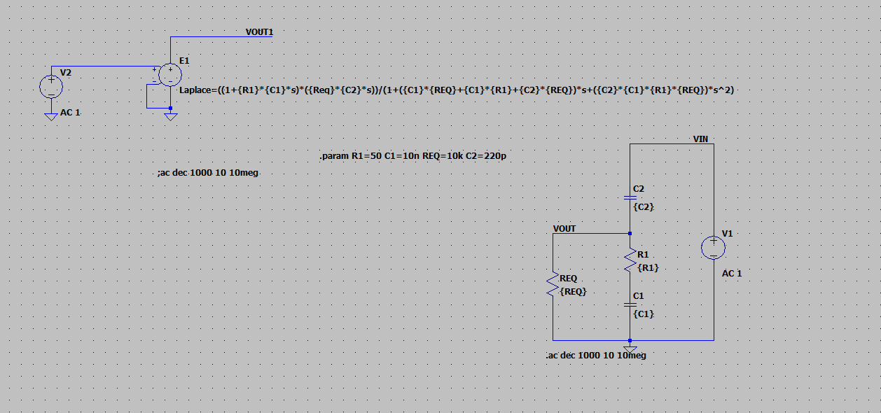
I'm looking for a way to do a Bode plot of the following transfer function from this schematic:

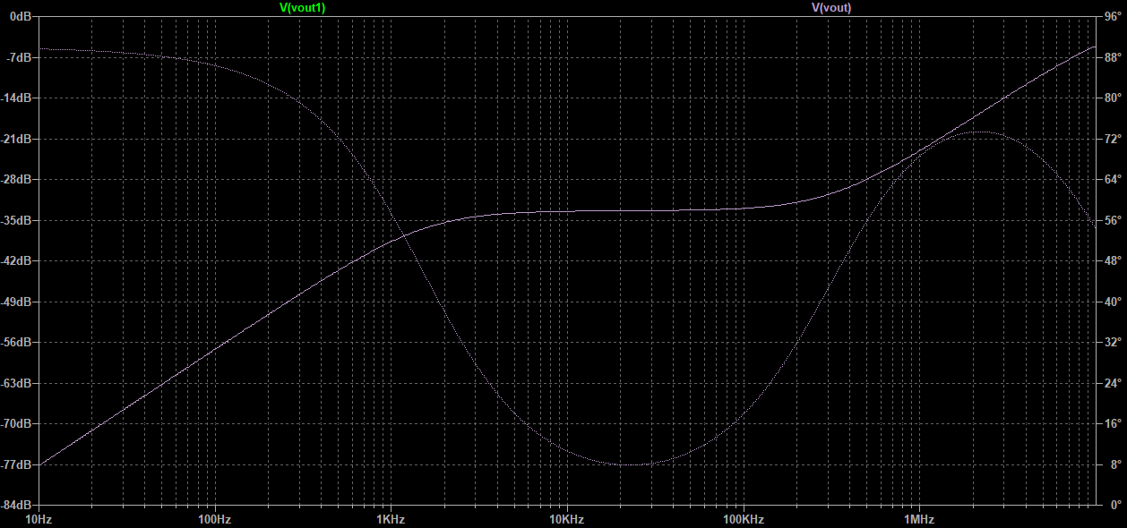
enter image description here

enter image description here

I tried to find the transfer function and finally got this:

enter image description here

\$Z_1=\frac{1}{2\pi R_1 C_1}=159\ \mathrm{kHz}\$ (1st order)

\$Z_2=\frac{1}{2\pi R_{EQ} C_2}=54.4\ \mathrm{kHz}\$ (1st order)

\$P_1=\frac{1}{2\pi \sqrt{R_1 R_{EQ} C_1 C_2}}=93.1\ \mathrm{kHz}\$ (2nd order)

The transfer function seems to be OK (simulation in Laplace in LTspice match with the simulation with schematic), but I didn't succeed to do the asymptotic Bode diagram "by hand". Maybe I miss something with the value of poles/zeros?

\$\endgroup\$
4
  • \$\begingroup\$ I don't understand your question. LTspice performs a Bode plot for you with the .AC card, as you show. You set up the AC 1 source already, too. Is it that you want the inverse? Rather than Vout/Vin you want Vin/Vout? Why? Oh, well. Just go to the plot and right-click the title that says V(VOUT) and make it 1V/V(VOUT) and you are likely done. (You can also directly plot s-space equations, too.) \$\endgroup\$ Commented Feb 17 at 22:48
  • \$\begingroup\$ Hello and thanks for your reply. Well the goal is not to simulate it but do the derivation in order to do by hand the asymptotic Bode diagram. I have the equation but pole/zero and order doesn't match with the result from LTspice. My question is, does my equation is false (from the circuit) ? or maybe I'm wrong with Bode diagram method with 2sd order form... \$\endgroup\$
    – exolune
    Commented Feb 17 at 23:39
  • \$\begingroup\$ With or without REQ present? And I still don't understand why 1/Vout. From what I see and from what a transfer function usually is, it should be Vout/Vin such that Vout = Vin * TF. So I think I'm still a little confused. \$\endgroup\$ Commented Feb 18 at 1:02
  • \$\begingroup\$ A transfer function Vout/Vin requires two nodes for defining Vin and Vout. Question: At which node do you define Vout? \$\endgroup\$
    – LvW
    Commented Feb 18 at 8:20

1 Answer 1

3
\$\begingroup\$

Expressing the transfer function (TF) the right way is often the key to figure out its asymptotic response. A well-organized or well-ordered expression was designated as a low-entropy result by Dr. Middlebrook in his classes on analytical techniques.

With a well-written transfer function, you should infer the position of the poles, zeroes and gains for instance, naturally figuring out the asymptotic response or the approximate Bode plot. And later on determine the components values to build the circuit. So it's truly a design-oriented analysis or D-OA, another acronym forged by Dr. Middlebrook. Your expression was probably derived using brute-force analysis and could be advantageously reorganized.

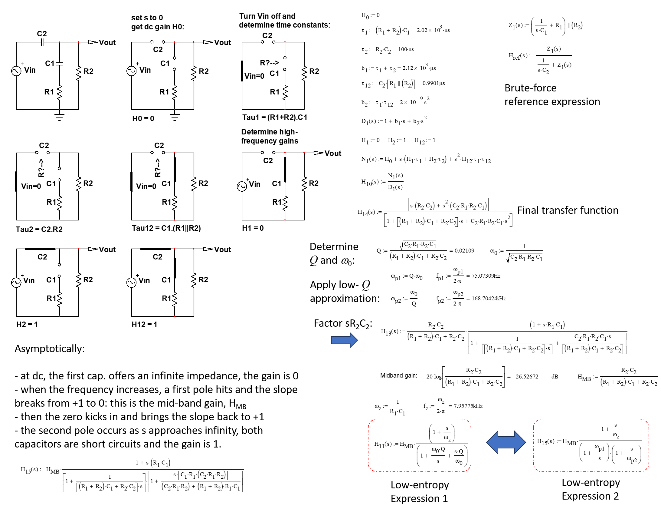
In my analysis, I have applied the fast analytical circuits techniques or FACTs that I described in the last book that I have released on this topic. The idea is simple: determine the gain \$H_0\$ of the circuit at dc for \$s=0\$ and then, turn the excitation off to determine the time constants of the circuit. You do it by temporarily disconnecting one of the energy-storing elements - you only have capacitors in this 2nd-order circuit - and you "look" through the connecting terminals to determine the resistance \$R\$ you see while the ac source \$V_{in}\$ is replaced by a short circuit. Then, you find the various \$\tau=RC\$ to form the denominator. The numerator can be obtained using a null double injection (NDI) or, in a simpler manner, by determining high-frequency gains, later combined with the time constants you already have. What is cool is that, very often, you can inspect the circuit without writing a line of algebra. See the flow below:
enter image description here

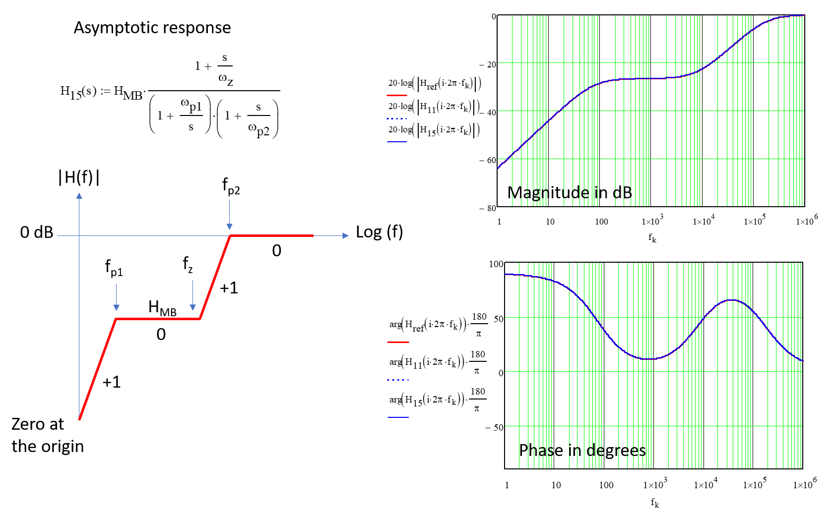
With an expression now featuring a mid-band gain, a zero and two poles, you can construct the asymptotic response of this transfer function. The plots in the right side confirm the approach:
enter image description here

Obtaining a sound expression for the transfer function is usually not the final step when analyzing a passive or active circuit. It is important to shape the result and organize it so that it tells you what it does and how you can use the expression to calculate the components values. These are the principles hidden behind the terms low-entropy expressions and D-OA.

\$\endgroup\$

Your Answer

By clicking “Post Your Answer”, you agree to our terms of service and acknowledge you have read our privacy policy.

Not the answer you're looking for? Browse other questions tagged or ask your own question.