1
\$\begingroup\$

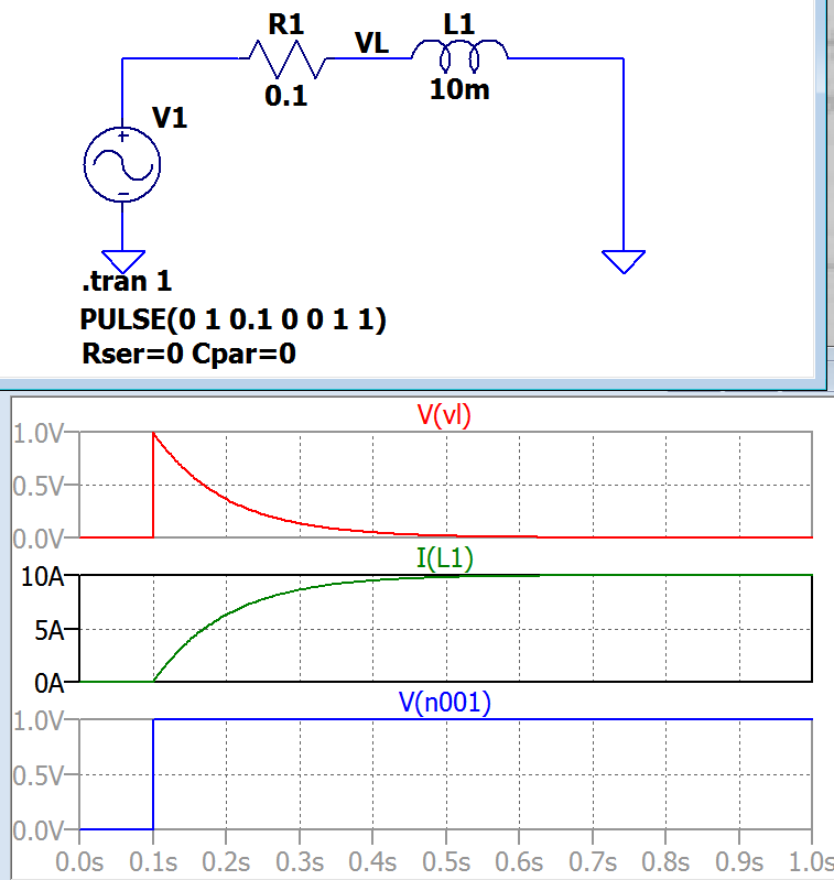
Below is an RL circuit and transient response plots of the inductor voltage V(vl) and current I(L1). V1 = V(n001) is the voltage applied to the circuit at time 0.1sec. (I set all series and parallel resistances and capacitors of source and inductor to zero for simulating a pure RL circuit)

enter image description here

What is happening above is that, the moment the switch is ON the inductor immediately opposes the current change and inductor voltage at that moment jumps to the voltage of V1. And current starts from zero so at t=0.1 I = V1 - VL = 0. These can be seen in the above plots.

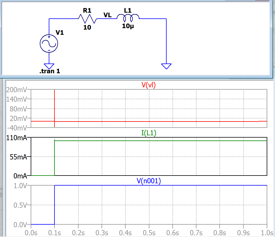
But now when I change the values of the inductor and the resistor as in the circuit below things do not follow the same logic:

enter image description here

As you see the inductor current again starts from zero at time t=0.1sec; which means the inductor voltage should again be equal to the source voltage V1 at time t=0.1sec. But the inductor voltage is VL 200mV in the above plot which confused me.

When I reduced the rise time of the rising edge of the switch the VL became equal to V1 again which is 1V. I think texts consider duration of the switching action is in infinitesimal amount of time.

Does the transient theory considers rising edges almost 0 seconds? And what is the relation between the rising edge of the switching and the initial inductor voltage here?

In other words how can the rising edge effect on the inductor voltage can be explained or formulated here?

EDIT:

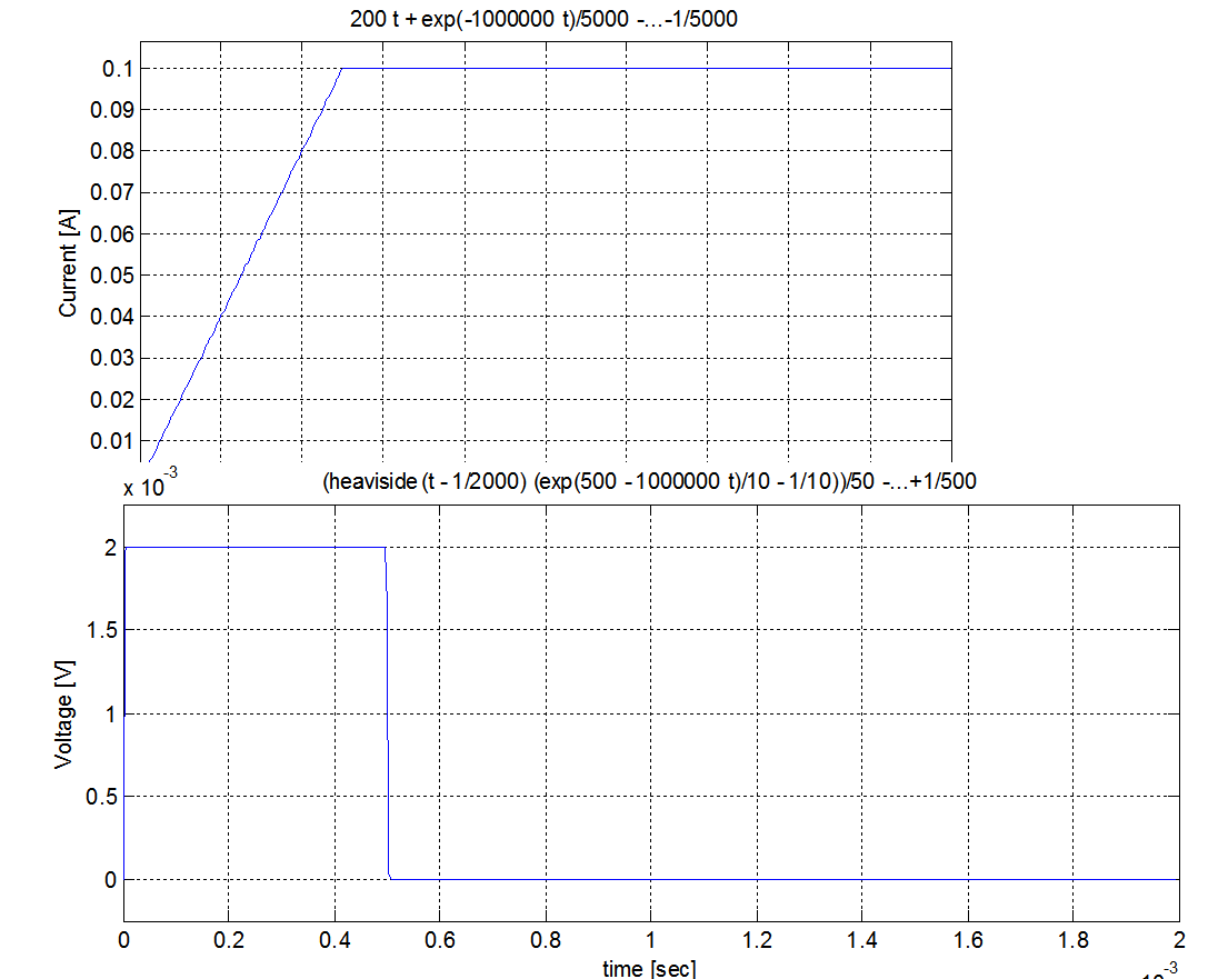
Solving this with Laplace and plotting in MATLAB gave the same results.

Here is what I did in MATLAB:

(Got help from the math guys here for V(s))

clear all;
clc;
syms s t

R=10;%resistance
L=10*10^-6;%inductance

a=1;%final voltage 1V
t1=0.0005;%rising time for the switch
m=1/t1;%slope of the rising edge

V = (-m*t1*exp(-s.*t1))./s + m*(1-exp(-s.*t1))./s.^2 + a*exp(-s.*t1)./s;%V(s) switch voltage
I = V./(R+s.*L);%current in s domain
VL=V-I.*R;

y= ilaplace(VL,t);%inverse Laplace

ezplot(y,[0,0.0004])
ylabel('Voltage [V]')
xlabel('time [sec]')

grid on;

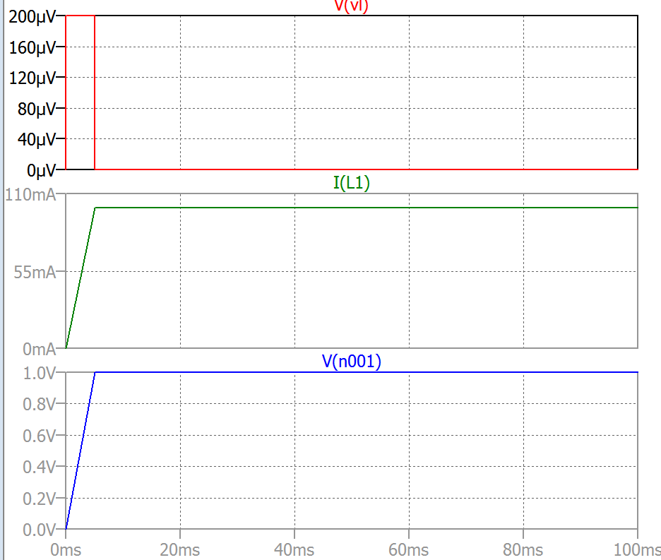
Both in LTspice and MATLAB I set the rising time as 0.0005 sec.

Here are the plots from both LTspice and then MATLAB:

enter image description here

enter image description here

It seems like results agree. So it seems LTspice does not calculate anything wrong here. Its just if the rising edge is slow thats what expected.

Do you agree?

\$\endgroup\$
16
  • 1
    \$\begingroup\$ To your last question: You cannot easily mathematically formulate Spice's behavior. That's what you are asking to do. Spice has a whole slew of different "algorithms" it applies in setting things up and in then numerically analyzing them. Although with enough time and money it would be possible to construct and apply all the needed mathematics to attempt to "describe" an implementation of Spice, it's completely backwards thinking to bother with it and a waste of effort. You just need to understand why and how to use Spice properly, is all, and to recognize garbage when you see it. \$\endgroup\$
    – jonk
    Commented Jun 24, 2017 at 17:01
  • 1
    \$\begingroup\$ Yes. But now your question is different and evolving. You can just use nodal analysis, but you still need to know the exact description of the stimulus, too. You are being very "hand-waving" about that stimulus. So, question. Do you understand how to use 's' as a complex value (either as cartesian or else as Euler's polar formulation) representation of exponentially growing sinusoids, damped sinusoids, pure sinusoids, growing exponentials, and so on? And also familiar with Fourier transforms of arbitrary combinations, or Laplace? An answer depends on your mental toolsets. \$\endgroup\$
    – jonk
    Commented Jun 24, 2017 at 17:12
  • 1
    \$\begingroup\$ No its not evolving reread it. \$\endgroup\$
    – user1245
    Commented Jun 24, 2017 at 17:14
  • 1
    \$\begingroup\$ @user134429 To go from the t-domain to the s-domain you use the Laplace transform. \$\int_0^\infty f_t\cdot e^{-s t}\:\textrm{d}t\$, where \$s \in\mathbb{C}\$. You will need to do this in parts for a narrow ramp where \$f_t=0, t \le t_0\$, \$f_t=1, t \ge t_1\$, and \$f_t=k\cdot t\$, in between. Use the unit-step function to help. Also, consider analyzing the derivative of your function, instead, if you feel that's easier (I think so.) \$\endgroup\$
    – jonk
    Commented Jun 24, 2017 at 18:22
  • 1
    \$\begingroup\$ @user134429 I just read that link you provided. Hehe. Almost exactly what I suggested, both with the derivative approach as well as the parts. ;) Nice to see my head is still screwed on right. \$\endgroup\$
    – jonk
    Commented Jun 24, 2017 at 18:44

3 Answers 3

2
\$\begingroup\$

But the inductor voltage is VL 200mV in the above plot which confused me

The timing of the event is a hundred thousand times quicker in the 2nd scenario so you need to home in on that much smaller event and set up your simulator so that its default step parameter is sufficiently small to properly evaluate the initial voltage across the inductor. It's a sim problem and you need to be more understanding that sims are not perfect.

L/R determines the time constant and in the first scenario L/R = 100 ms. In the 2nd scenario L/R = 1 us.

\$\endgroup\$
4
  • \$\begingroup\$ Yes the problem is rising edges is not sharp enough. But this means the inductor voltage is dependent on the sharpness of the rising edge. How can we mathematically formulate the relation between the sharpness of the rising edge and the inductor initial voltage? Let me put is this way I think the simulator is not wrong but there is a relation between the very slow rising edge and the inductor voltage here? I dont know if I could explain my question \$\endgroup\$
    – user1245
    Commented Jun 24, 2017 at 16:56
  • \$\begingroup\$ Use maths, V = L di/dt is the starting point so, if you differentiate voltage to get dv/dt you can set that to a constant (i.e. equivalent to a rise time in volts per second) and derive what the double differential of current is mathematically with respect to time. Or just set the sim to show the right result by setting the time step period appropriately. Either way is up to you. \$\endgroup\$
    – Andy aka
    Commented Jun 24, 2017 at 17:19
  • \$\begingroup\$ I edited my question and concluded SPICE calculates things right. Its just the slow rising edge causes this. If Im not wrong. Please see my edit \$\endgroup\$
    – user1245
    Commented Jun 24, 2017 at 19:24
  • \$\begingroup\$ I never had any doubt that if you set things up correctly then you will see correct results. \$\endgroup\$
    – Andy aka
    Commented Jun 24, 2017 at 19:28
1
\$\begingroup\$

The switch rise time affects the frequency spectrum of the “step” applied to the system. It’s only natural that if you retune the system to much higher frequencies, but use a slow (low-frequency) step, you will be observing something quite different than in the original circuit: the circuit’s response is so much faster than the stimulus, that the stimulus “appears” to the circuit as if it was stationary.

In SPICE, the simulation setup must match the time scale of the events of interest. If you want to see behavior of a system with a time constant of 1us, you can’t be setting up a 10s long simulation: the default time step will be inappropriate. Make the simulation much shorter - say 20us long, with the pulse at 1us. And you’ll see what you expected then.

\$\endgroup\$
0
\$\begingroup\$

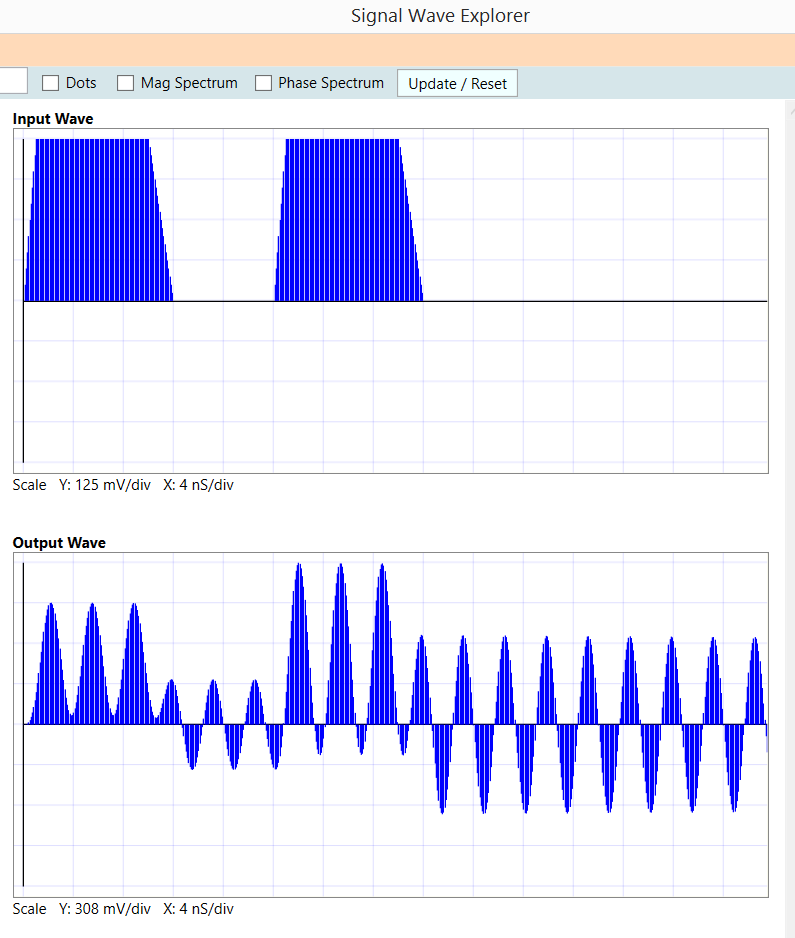
what happens if the falltimes of the input pulse.....are same as the ringing frequency of the system

enter image description here

With some care, you can cancel out any ongoing ringing during the ramp up or down, and continue on with a new amplitude and phase. Its all about the ENERGY you inject into the resonant circuit, during the ramp/transient.

\$\endgroup\$

Your Answer

By clicking “Post Your Answer”, you agree to our terms of service and acknowledge you have read our privacy policy.

Not the answer you're looking for? Browse other questions tagged or ask your own question.