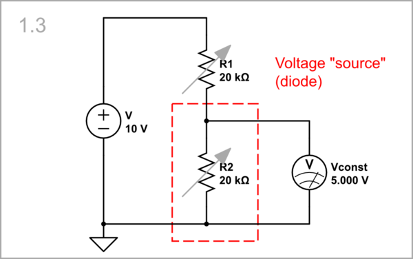
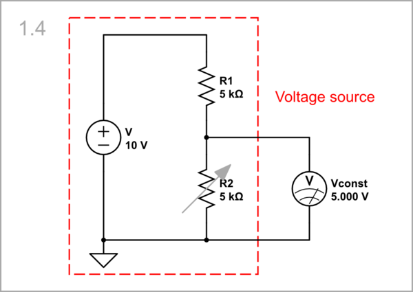
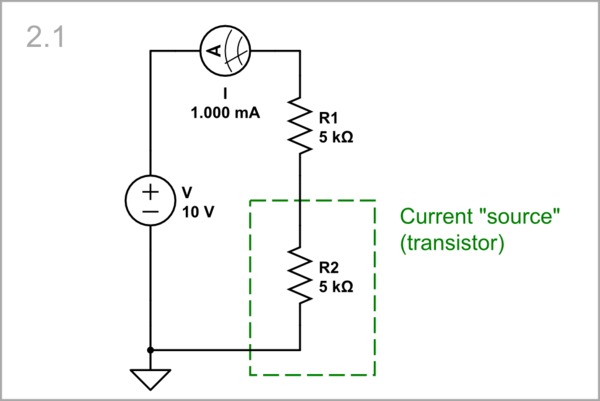
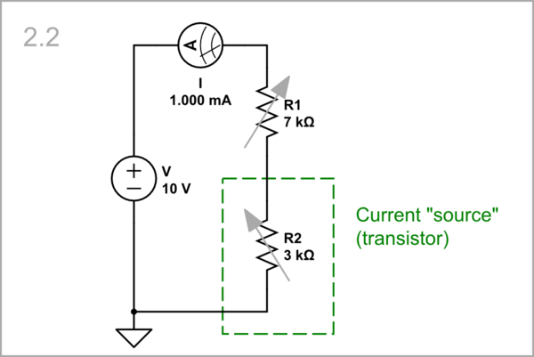
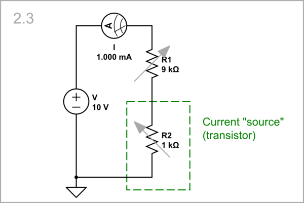
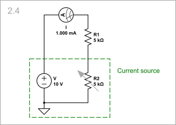
There are only two quantities that can be considered fundamental, or "real", in the sense that they actually exist, and those are voltage and current. Resistance is artificial, a contrived quantity that merely describes the relationship between voltage and current.
Voltage across some component, and current through it, are usually related somehow. For instance, for a resistor we find that the two values are directly proportional to to each other. That is, if you double the voltage \$V\$ across a resistor, the current \$I\$ through it also doubles, or if you halve current \$I\$, voltage \$V\$ is halved too. That particular relationship is called "Ohm's law":
$$ V = R \times I $$
The constant of proportionality in this relationship is resistance \$R\$. This formula only applies to resistors. For other elements, such as voltage sources, current sources, capacitors, diodes and so on, the relationship between current and voltage is not directly proportional. For instance, the current \$I\$ through a silicon diode, as a function of the voltage \$V\$ across it is:
$$ I = I_S\left(e^{\frac{qV}{kT}}-1 \right) $$
It will be helpful to draw graphs of voltage vs. current for three components, a 10V voltage source (blue), a 1A current source (red), and a 2.5Ω resistor (green):
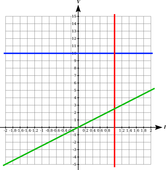
The key features of these graphs are:
The voltage source (blue) has a constant voltage across it, regardless of the current through it. It is a straight, horizontal line, with gradient (slope) \$\frac{dV}{dI} = 0\$. Notably, current and voltage are independent of each other, when current changes, voltage does not.
The current through the current source (red) is fixed at 1A, regardless of the voltage across it. It is also a straight line, but this time it's vertical, having slope \$\frac{dV}{dI} = \infty\$. Again, current and voltage are independent; when voltage changes, current does not.
The resistor (green) is not vertical or horizontal. Its slope is non-zero and finite: \$\frac{dV}{dI} = 2.5\$. The line passes through the origin \$(I=0, V=0)\$. This is a graph showing direct proportionality between \$V\$ and \$I\$. When current changes, voltage does too, in proportion to the change in current, and vice versa.
That facts that neither voltage source nor current source have any relationship at all between voltage and current (they have infinite/zero V-I gradients), and that their V-I curves do not pass through the origin, are clear indicators that the concept of resistance is not applicable to sources. Resistance implies direct proportionality between voltage and current, a behaviour which sources simply do not exhibit.
The short answer to your question is that a voltage source "outputs" only a voltage, and doesn't impose any constraint on the current through it. A current source "outputs" only a current, imposing no constraint on voltage across it.
Perhaps the simplest demonstration of a source's independence of voltage and current is when we connect a current source in parallel with a voltage source:
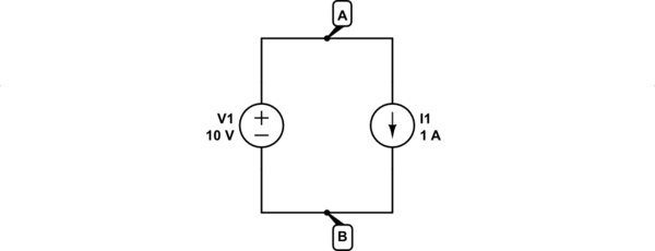
simulate this circuit – Schematic created using CircuitLab
You might think that there's a conflict here, but there isn't. The only job of voltage source V1 is to apply a fixed potential difference of 10V between A and B. The only job of current source I1 is to ensure that 1A flows around the loop. Neither of those roles are in conflict with the other. Source V1 has no problem with I1's insistence that current be 1A, and source I1 has no problem with V1's insistence that the voltage across it be 10V.
There's no ambiguity about the current, here, or the voltage, and either source can choose the conditions that it "imposes" without the other so much as batting an eyelid. In other words, where does resistance play a role here? No equations that you derive for the behaviour of this circuit make any mention of "resistance" at all. There are two equations:
$$ V = 10V $$
$$ I = 1A $$
That's it. Where's the R?
If you insist on assigning some kind of resistance value to a source, then you must first define what that resistance means. A practical definition of resistance in these circumstances goes as follows: resistance is the ratio of change in voltage to change in current:
$$ r = \frac{\Delta V}{\Delta I} $$
In mathematical treatments you will normally see the above relationship written:
$$ r = \frac{dV}{dI} $$
If you paid attention in math class, then you'll understand that this is referring to the gradient (slope) of the graph of \$V\$ vs. \$I\$, at some particular point \$(I, V)\$ on that graph. I've used a small \$r\$ to indicate that this is dynamic resistance, as distinct from ohmic, which applies only to resistors.
By that new definition, the dynamic resistance of a voltage source will be the gradient of its \$V\$ vs. \$I\$ plot, which is zero:
$$ r_{V1} = 0\Omega $$
The dynamic resistance of a current source is also the gradient of it's \$V\$ vs. \$I\$ plot:
$$ r_{I1} = \infty\Omega $$
The dynamic resistance of a resistor is the same as its ohmic resistance, because the gradient is constant, and proportionality is direct. For a resistor, Ohm's law is always true, for all values of \$V\$ and \$I\$, and both \$V\$ and \$I\$ are able to change:
$$ R = r = \frac{dV}{dI} = \frac{V}{I} $$
Dynamic resistance is a very useful concept. For any component that does not have a linear (straight line) \$V\$ vs. \$I\$ curve, the gradient of the curve changes as you vary either voltage or current. Take the silicon diode, for example. Its V-I curve is the blue line here:
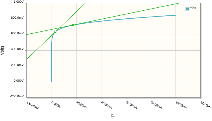
The response of the diode to very small changes in current is different depending on where you "reside" on this graph, since the gradient of the curve is different everywhere. In other words, by passing an average (DC) current of 18mA through the diode, and making small ±100μA fluctuations (the "AC signal") , the resulting voltage changes across the diode will be much smaller than the changes you can expect if the average DC current through it were 3mA. This permits you to control gain.
Cells and batteries of cells are voltage sources. They maintain a constant potential difference chemically (at least until they are depleted of energy, or over-charged to destruction). Their chemical and physical construction are such that charges at one end tend to have a fixed amount of potential energy with respect to charges at the other terminal. How that happens is for the chemists to know.
Other ways exist to produce a fixed potential difference, such as charge pumps, and it's sufficient to design a circuit that constantly monitors some potential difference, and if it changes, take some action to restore it. "Pump faster or pump slower", in the same way you occasionally pump air into a tyre that has a slow leak, to maintain constant pressure.
At the moment I can't think of any current sources that are able to self-regulate like chemical cells, although probably some such thing exists. However, it's possible to build regulators that maintain a constant current flowing through them, in the same way that voltage regulators do; monitor and adjust.
At the risk of confusing voltage sources with current sources, in practice it's probably easiest to think of a current source as something that varies its own potential difference to whatever value is required to obtain the requisite current through whatever's connected to it (and, consequently, itself). The result is the behaviour you would expect from a current source; current through it remains fixed while the voltage across may vary. As long as there's no functional difference, there is no distinction between a current source and a voltage source that varies voltage to maintain constant current.
By that same argument, you might consider a constant voltage source to be something that varies current, to whatever amount produces exactly the correct fixed potential difference across it. Again, a variable current source that maintains a constant potential difference is functionally identical to a fixed voltage source. Both practically and mathematically there's no distinction.
However you envisage these sources, they each only represent a single quantity in the simultaneous equations that you derive for any system. When you see a voltage source in a schematic, all you know about it, until you solve for all the other variables, is the voltage across it. For a current source in a schematic, all you know (until the system is solved) is the current through it. How they work is actually irrelevant in the analysis.
Cells aside, to build practical, active voltage and current sources is not trivial. When you see a source in a schematic, it represents an abstraction of something that, in practice, may have substantial complexity, consisting of transistors and/or op-amps, and other elements, whose role is to make continuous adjustments to maintain some fixed voltage or current.
In the analysis, though, their behaviour is truly trivial. When you see a voltage source in a schematic, you know the potential difference between two points. That's all. When you see a current source, you know the current in that path. That is all.


