Short answer
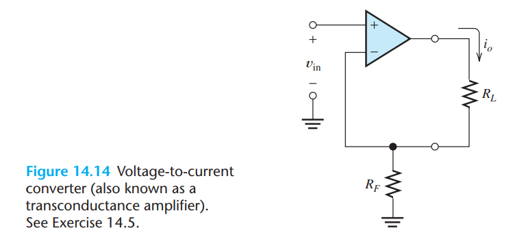
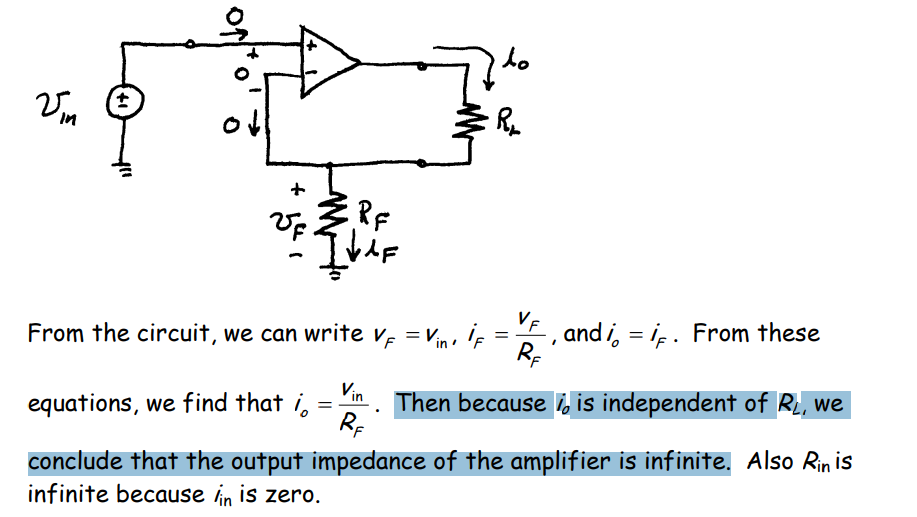
The circuit presented by OP is a constant current source (op-amp and current-setting resistor RI) that supplies a "floating" load RL. Through negative feedback, the voltage across RI is maintained equal to the input voltage (Vin). As a result, the current flowing through both RI and RL depends only on Vin and RI, following the equation IL = Vin/RI.
Beyond IL = Vin/RI
Such "textbook explanations" using established terms that have become verbal clichés do a good job in many cases but not when the goal is to understand the circuit solution. Understanding is different from knowing and doing. It requires you to understand the idea, the concept, the principle... Apparently, that is why the authors of the famous book from which the OP's question was born showed this necessity in the book title, but for some reason they left it to us to do it. Then let's take advantage of this unique opportunity and discover the principles on which this class of circuits is built. This will give the OP a good foundation in their future encounters with similar circuit solutions.
Classic negative feedback solution (OP's circuit)
Basic idea: To set a current of a certain value through the load according to the principle of negative feedback, we need to convert it to a voltage (because our devices work with voltage) and compare it with the input voltage. Then we vary the current until the difference between the two voltages becomes zero. As a result, IL = VRI/RI = Vin/RI.
Implementation (conceptual circuit): For this purpose, we (the "op-amp" ) apply a variable voltage VOA to the RL-RI network. Then we subtract in series manner the voltage VRI from Vin, and properly apply the result to the op-amp differential input. Finally, we vary the voltage until reach equilibrium (VNI = 0 V).
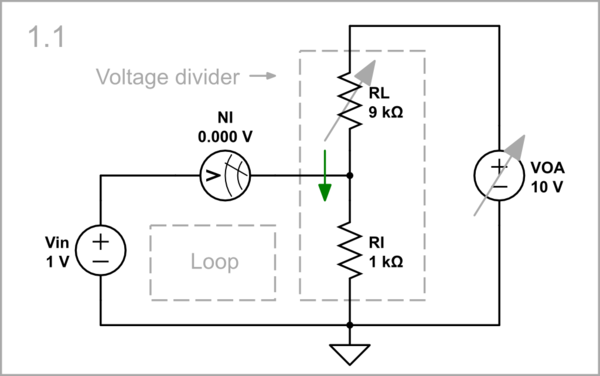
simulate this circuit – Schematic created using CircuitLab
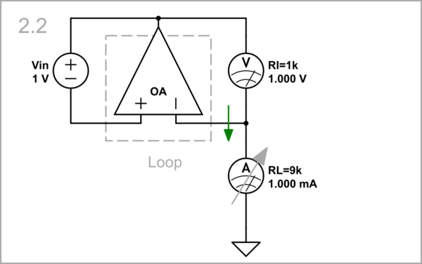
Op-amp non-inverting current source (OP's circuit): We can make an op-amp do this routine work. For simplicity, I have replaced the resistors with meters of the same internal resistance.
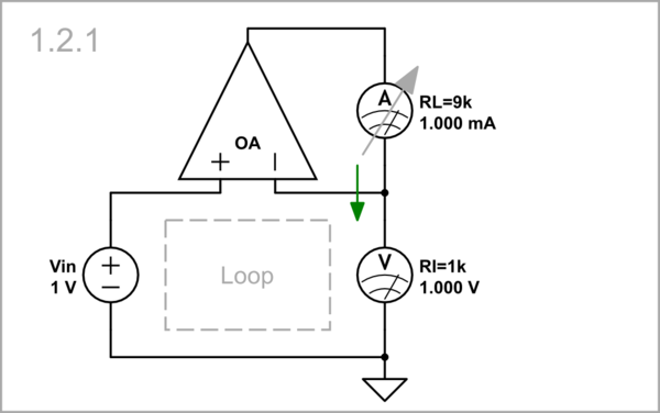
simulate this circuit
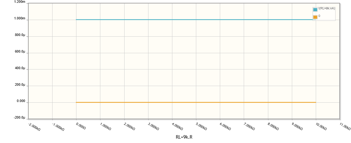
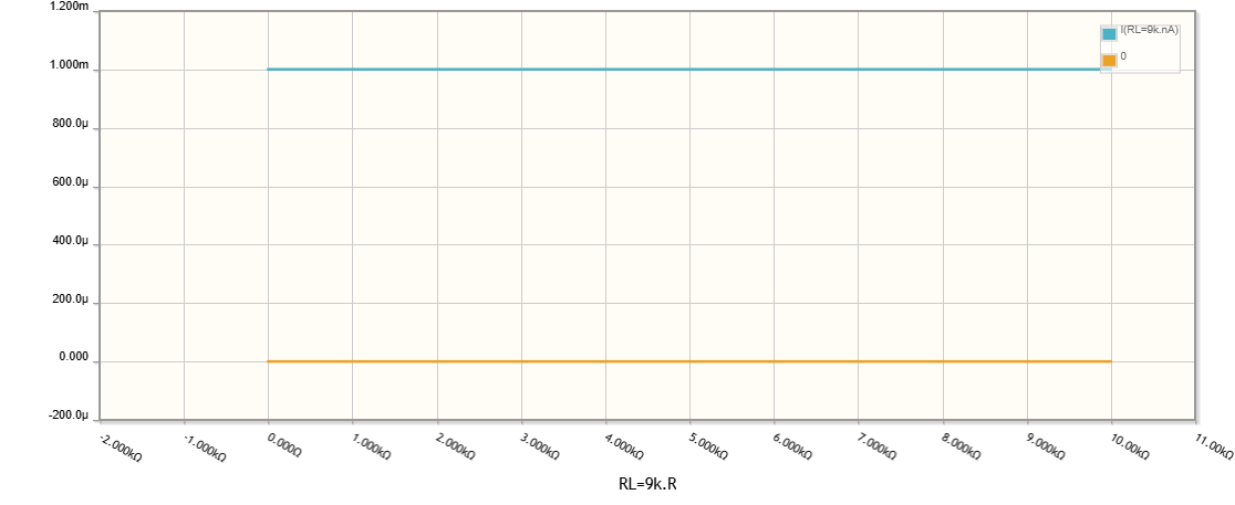
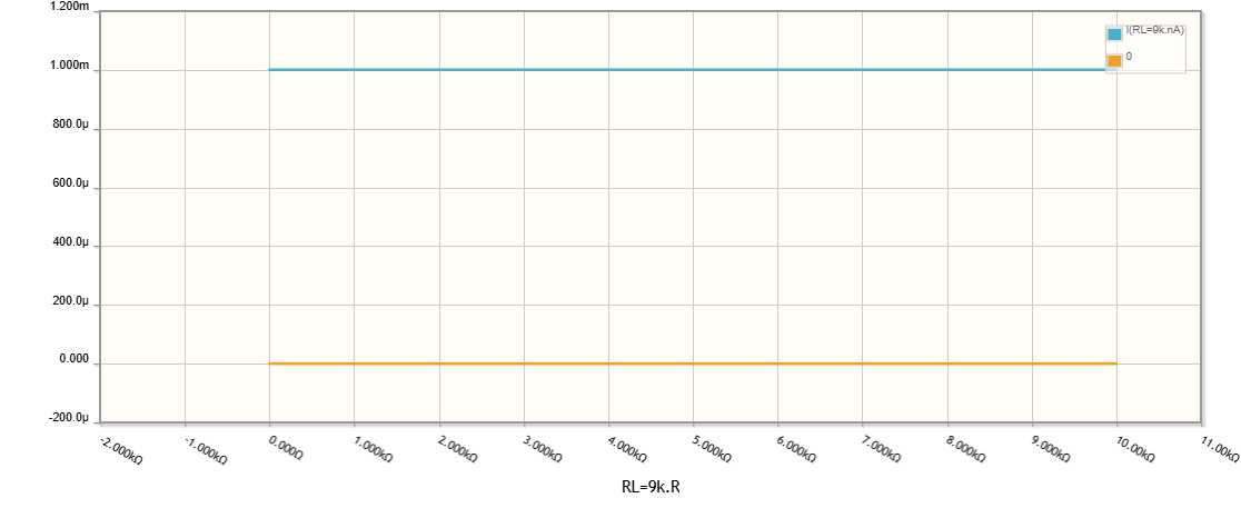
Let's investigate the current source at various loads (from 0 to 10 kΩ) by the help of the CircuitlLab DC Sweep Simulation. As you can see, the curve of the current (in blue) is absolutely horizontal.
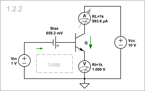
Transistor current source with emitter degeneration: This circuit solution has long been known in its transistor implementation. To make the circuit more perfect, I have added a bias voltage.
simulate this circuit
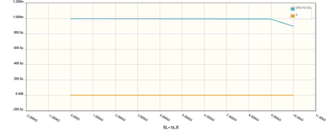
Problem: In the configurations above, both input voltage source and current-setting resistor are grounded but the load is "floating" which is in most cases inconvenient.
Negative feedback solution with floating input voltage source
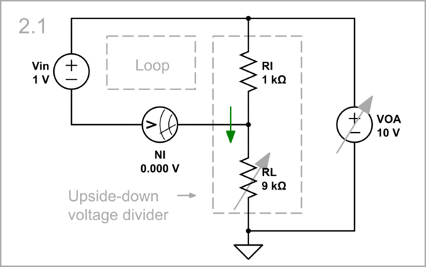
Conceptual circuit: We can swap the resistors so that the load is grounded but now the input voltage source is "floating". As you can see, Vin, RL and the null indicator NI are connected in a loop.
simulate this circuit
Op-amp circuit: Vin, RL and the op-amp differential input are connected in a loop.
simulate this circuit
Both negative and positive feedback solution (NIC)
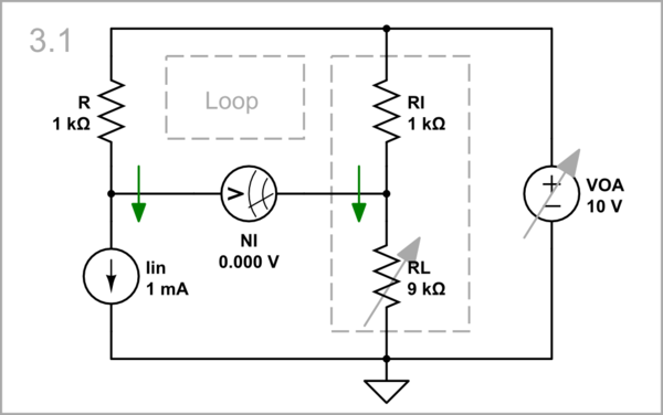
Conceptual circuit: The input source may be grounded if it is a current source.
simulate this circuit
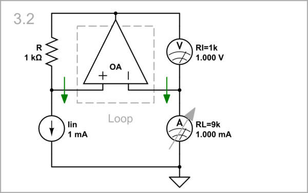
Op-amp current mirror: This is the odd negative impedance converter (NIC). The op-amp simultaneously changes the voltages at its inputs to reach equilibrium (VRI = VR).
simulate this circuit
No negative feedback solution (bootstrapped RI)
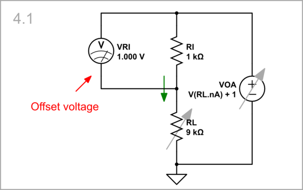
Conceptual circuit: Constant current can also be obtained without using the principle of negative feedback. If we are observant enough, we will notice that the voltage at the upper end of the current-setting resistor RI follows the voltage at its lower end. So we can add a constant offset voltage to the load voltage and apply it to the upper end of RI.
simulate this circuit
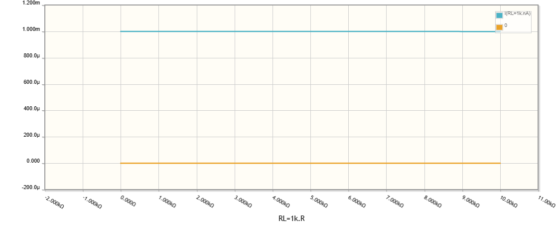
As you can see in the graphs beluw, the curve of the upper end is lifted by 1 V above the curve of the bottom end.


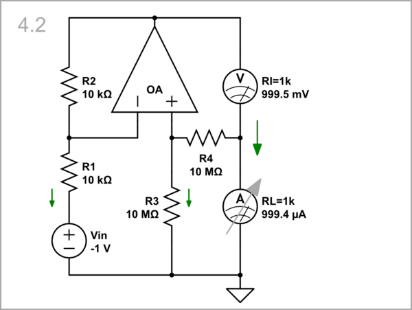
Improved Howland current source: This idea is implemented in the so-called "Improved Howland current source". The load voltage variations are amplified 1x and appear at the top RI end.
simulate this circuit
Inverting current source
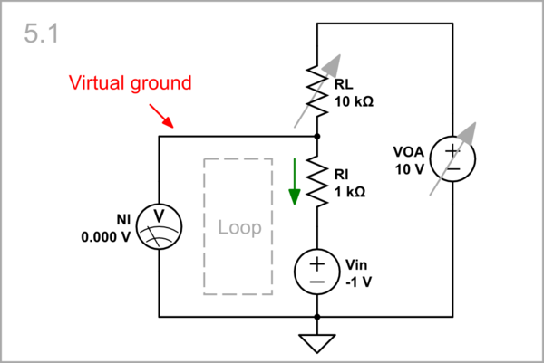
Conceptual circuit: Finally, let's see how the same idea is implemented through an inverting op-amp configuration.
simulate this circuit
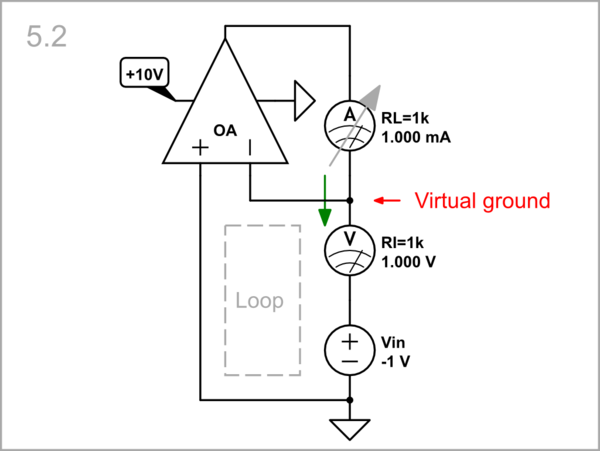
Op-amp inverting current source: Here, the voltage across the current setting resistor RI is subtracted from the input voltage and the result is zero (the so-called virtual ground). The load is virtually grounded which is better than to be floating. I have used an op-amp with supply ends to show the load limitations.
simulate this circuit
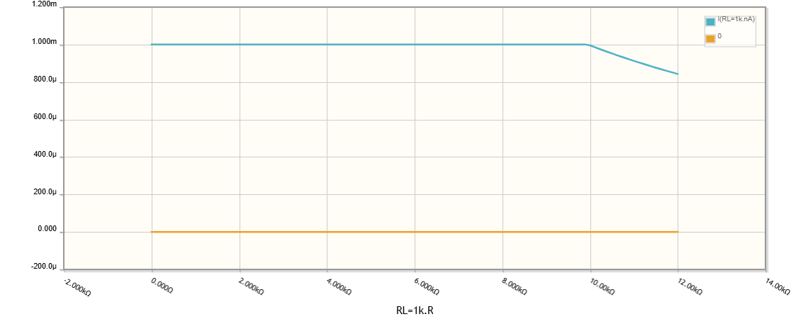
When RL exceeds 10 kΩ, the op-amp output voltage reaches the supply rail and stops changing.
What "infinite output impedance" means
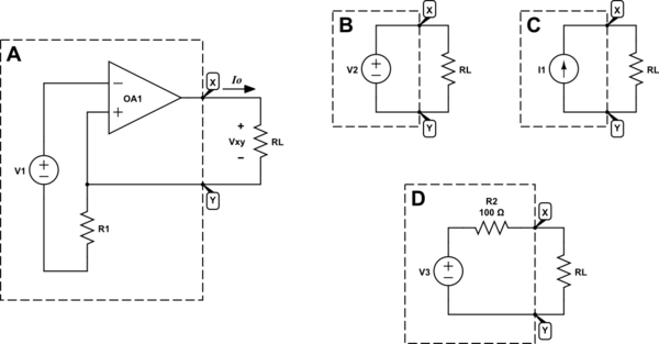
The main property of a constant current source is that its current does not change when we change the resistance of the load (the voltage across it). But if we don't want them to understand us :-), we say that "its output impedance is infinite". What is actually going on in the OP's circuit that this is the case?
Regardless of the specific implementation, the same thing happens: When we start increasing the load resistance RL, the op-amp current source starts increasing the load voltage VRL by the same amount so the ratio VRL/RL = IL does not change. So the main idea in these constant-current circuits is dynamic voltage.
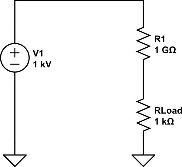
The same effect can be achieved with infinite "static" (constant) voltage and infinite constant resistance but the losses will be great.
So the end result for both implementations is the same - infinite resistance, but the nature of that resistance is different:
In the first case it is not physical resistance but dynamic voltage that creates the same voltage opposition as the physical resistance (aka "bootstrapping").
In the second case it is physical resistance.

