2
\$\begingroup\$

I suspect this may not be possible but I wanted to check with the hive mind first.

I have a float sensor with a resistance range of 22 to 220 ohms that needs to drive a gauge that shows full at 7 ohms and empty at 50 ohms. I know that if I put a 65 ohm resistor in parallel with the sensor I can get the 22-220 range down to 16-50 ohms but I wonder if there is a way to get closer to the ideal 7-50 range.

\$\endgroup\$
0

2 Answers 2

1
\$\begingroup\$

Your solution of using a 65 \$\Omega\$ resistor in parallel with your sensor will indeed change the range of the composite resistance to 16-50 \$\Omega\$. However, composite resistance will not be linear with respect to the sensor's original resistance. For example when the sensor's resistance is 65 \$\Omega\$, (i.e. closer to 22 \$\Omega\$ than to 220 \$\Omega\$), the composite resistance will be 32.5 \$\Omega\$ (i.e. closer to 50 \$\Omega\$ than to 16 \$\Omega\$).
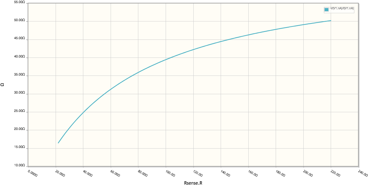
enter image description here

Now, assuming that such non-linearity is acceptable to you, I have tried multiple ways of combining multiple resistors in parallel and in series with your sensor, in ways that would give a low composite resistance of 7 \$\Omega\$ and a high composite resistance of 50 \$\Omega\$. However, in each case, my equations gave me a negative resistance value for one of the resistors.

I don't have a rigorous proof, but I would answer the question of whether you can get a 7-50 \$\Omega\$ range for a composite resistance with a NO.

Of course, if you are permitted to use active devices (i.e. amplifiers) then the answer would become YES.

\$\endgroup\$
2
  • \$\begingroup\$ Active devices are allowed (12v supply) but I'm no good at analog so my solution would be a small microcontroller with a DAC. \$\endgroup\$
    – davecove
    Commented Mar 21 at 15:47
  • \$\begingroup\$ ... except I just noticed that they don't make digitally controlled pots in anything close to 7 ohms... 0.8k to 1.6k was as close as it gets. No one seems to make voltage controlled pots either. Since the sensor is just limiting current through the gauge's coil I guess I could add a resistor in series with the sensor, read the voltage drop across it and then use a transistor controlled by the uC's DAC output voltage to produce the same current that the gauge would expect from a sensor with the proper range. \$\endgroup\$
    – davecove
    Commented Mar 21 at 17:46
1
\$\begingroup\$

If you consider as a measure of goodness the sum of the squares of the differences between what you get and what you want at the lowest and at the highest resistances, a minimization function reveals that a 61.9 ohm resistor will yield the measure 266, lower than the measure 270 you get with a 65 ohm resistor. That's the best you can do--using this measure--with a single parallel resistor.

You could get a much better result if you were willing to add a circuit to map the one range into the other. In effect, you would force the results for your resistor values to match the ones appropriate for you gauge. Is that option available to you?

\$\endgroup\$
2
  • \$\begingroup\$ Yes, but as mentioned above, analog is not my strong suit so now that I know what I need is not possible with passive elements I'll probably solve it with a microcontroller. \$\endgroup\$
    – davecove
    Commented Mar 21 at 15:49
  • \$\begingroup\$ The digital approach is turning into a can of worms since digitally controlled pots in the range I need don't exist (not even close), but I don't know how to design a circuit like you describe. \$\endgroup\$
    – davecove
    Commented Mar 21 at 17:52

Your Answer

By clicking “Post Your Answer”, you agree to our terms of service and acknowledge you have read our privacy policy.

Not the answer you're looking for? Browse other questions tagged or ask your own question.