I'm looking at a brand new foot pedal for a Tungsten Inert Gas (TIG) welder. This foot pedal uses cascading potentiometers to send a signal to the welder control system. I'm getting unusual results when I verify the pedal using a Volt Ohm Meter. I'm measuring resistance between the wiper terminal and 'ground' terminal on the pot. Pedal off = 0 ohms, slight push 5K ohms ,push more... 10k up to 12.5k ohms at 3/4 full push. If I go beyond that however, the resistance reduces from 12.5k down to 1.6k
This is a brand new pedal (yup, off of ebay.) Its obviously never been used. The pot has a smooth shaft with a spur gear attached. The foot pedal has a 2" gear rack attached.. when you push the pedal down the rack moves and rotates the gear. The movement feels extremely smooth. I can't find the spec for the pot for that manufacturer but I can find other manufacturers with virtually the same part #. It looks to be a liner pot, 300deg of motion. I don't have a lot of practical experience with potentiometers.
Here are my questions. 1) Does the 'hard' stop on a typical single turn potentiometer control full range of travel (i.e. zero ohms at one end of stop, max resistance at the other end of the stop) 2) How robust is the hard stop internal to the potentiometer? (Clearly with a foot pedal input the functional foot pedal stop should be something mechanical external to the fragile potentiometer. ) If the external mechanical stop was not set, and you pushed the pedal hard, would the stop just break off or would there be other issues? --3) Do they build rheostats with 300 degrees of function but withOUT an internal stop in them?? (That would make sense for exactly this type of application.. Manufacturer to provide range of motion control external to the pot. Mfgr to ensure alignment of zero and max set points. If manufacturer allowed the pot to spin too far, the function is off, but there would be no permanent damage to the potentiometer.)
Part number: RV24YN20S B503 Mfgr: Hungyun.com
No, I've not taken this pedal apart to isolate the pot.. I don't want any 'warranty' hassles from the seller.
Yes, I can reduce pedal travel to lock at the max observed resistance. I'll do that if I'm sure this isn't a different type of 'quality' problem which will cause issues later.
So hey, is the answer to #3 = yes, and I should just adjust the hard stop and move on?
Many thanks. Zip.
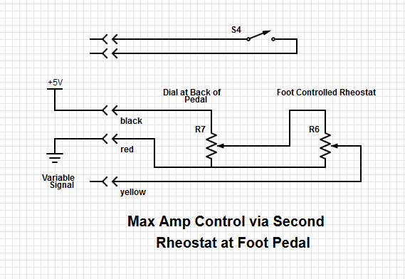
Update to add schematic and address some of the questions below:

This type of pedal is found on some 'low end' welding machines.. The side of the pedal has a dial with which you set the max. amperage. The foot pedal potentiometer allows you to easily change output amperage from zero to max amperage. Obviously its a simple signal back to the welder's output control system. For troubleshooting this new pedal, I removed an inspection panel allowing me to see inside the pedal. I can see clearly every wire connection. Nothing is grounded to the pedal steel chassis. I was very careful to ensure that both pots are actuated CW (when viewed from end of shaft). I was also very careful to ensure I have the wire and their attachments EXACTLY per the schematic I just now drew on digikey (scheme it)
For troubleshooting I have a nice fluke V-O-M reading between the red wire and the yellow wire with the "dial at back of pedal" set to zero. The 'back of pedal' pot is a RV28P B103 (10K ohms).
I think I'm doing this right.. do you agree? The other thing that is baffling me... I can understand a variable resistance going from 0 to big. What I don't understand is 0 to big back down to a lot less than big. I've never taken a potentiometer apart. I can understand 0 --> max ohms --> max ohms -->max ohms --> zero but never 0 --> max ohms --> some middle value. Can anyone explain?

