2
\$\begingroup\$

This is what Dave Tweed wrote in his post here about a floating power supply:

It simply means that the output side of the power supply is completely isolated from the input side, not even sharing a ground connection.

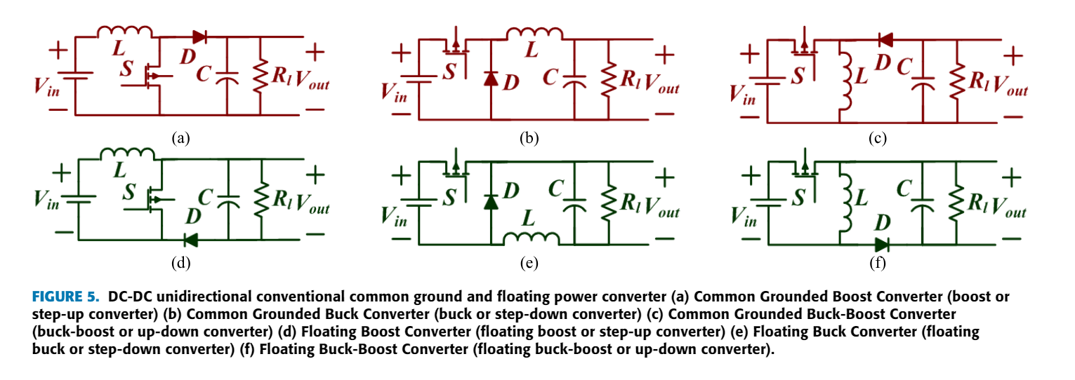
When I did a Google search, I found this image (from here) about a common grounded and floating output boost converter. The floating boost converter is connected to ground (assuming an ideal diode) in the second phase.

Can we still say that it's a floating converter? What is the correct definition of a floating output DC-DC converter?

enter image description here

Full image:

enter image description here

enter image description here

\$\endgroup\$
7
  • 4
    \$\begingroup\$ Those diagrams are most definitely not floating. They have an ohmic connection with V+ and ground. \$\endgroup\$ Commented Apr 8 at 16:31
  • \$\begingroup\$ @DrMoishePippik I'm also confused about the difference between 'floating' and 'isolated'. So, can we conclude that it's a mistake in the paper? \$\endgroup\$
    – hana
    Commented Apr 8 at 16:34
  • \$\begingroup\$ Your link is inaccessible without an account so, please provide an alternative source that is accessible or, embed images of the text that says what you assert. \$\endgroup\$
    – Andy aka
    Commented Apr 8 at 16:34
  • 1
    \$\begingroup\$ A supply might be isolated (for DC) by a transformer, for example; i.e., if one were to connect a source between an input line and output, no current would flow. \$\endgroup\$ Commented Apr 8 at 16:38
  • 2
    \$\begingroup\$ @DrMoishePippik they don't say isolated; they say floating (just in case you want to correct what you wrote). \$\endgroup\$
    – Andy aka
    Commented Apr 8 at 16:42

5 Answers 5

5
\$\begingroup\$

None of your drawings are isolated. You have a DC path between primary and secondary. Dave is correct: input and output are isolated from each other, being only magnetically coupled by a transformer. There is no DC or galvanic connection.

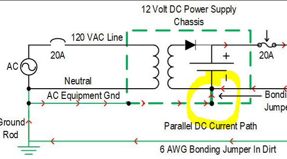
I have some sample drawings I drew some time ago for a project I worked on for a class project. One is isolated, and one is not. The secondary on the non-isolated side has the negative terminal grounded to the chassis. NEC electrical codes require electrical systems to be isolated from each other so a fault in one system will not flow in another system.

All shipyards use isolation transformers to break galvanic paths between ship and shore. Ship captains frown if you induce accelerated corrosion (DC current) to their superstructure, and large high-rise building managers also frown when you allow DC currents to flow through the steel structures.

The isolation transformer is the most powerful tool for power quality engineers. It yields up to 120 dB of CMRR isolation and allows you to establish a new ground reference point free of noise.

enter image description here

enter image description here

\$\endgroup\$
3
  • 1
    \$\begingroup\$ Thanks, but I think "floating" and "isolated" are two different concepts, and the question is about "floating". \$\endgroup\$
    – hana
    Commented Apr 9 at 3:58
  • \$\begingroup\$ No, sir, they are not different; you can't have one without the other. To float the output of a DC power supply, the very first thing you must do is isolate the output from the input. Once isolated, you can either Float the output or reference it to ground. There cannot be any galvanic or DC continuity between input and output. \$\endgroup\$
    – Dereck
    Commented Apr 9 at 14:29
  • 1
    \$\begingroup\$ Thank you. What you said seems good, but do you have any authentic references to support it? \$\endgroup\$
    – hana
    Commented Apr 10 at 8:00
4
+200
\$\begingroup\$

Definition of "Isolation"

In page 2 of the open-access paper, which is where the images you've quoted are coming from, it says:

Fig. 3 shows the classification of PEC to focus on DC-DC converter. DC-DC converters, classified into two main categories; Non-isolated and isolated. A non-isolated converter shares a common ground between input and load or with the floating load. Whereas, in the isolated converter, input and load terminal are electrically isolated [65]. Based on the direction of power flow through the converter, non-isolated and isolated converters classified into two sub-categories; one is unidirectional, and another is bidirectional converters. To provide isolation; the transformer and coupled inductors employed in the power converter. Which increase the conversion ratio of the converter, but also increases the cost, size and losses. Thus, the high frequency is the superior option to reduce the transformer and coupled inductor size.

Thus, according to the paper's own definition:

To provide isolation; the transformer and coupled inductors employed in the power converter.

Definition of "Floating" Within the Cited Paper

Now, what does the paper say anything about floating?

The power circuit of the conventional unidirectional common grounded boost, buck and buck-boost converters, depicted in Fig. 5(a)-(c). Whereas the floating output boost, buck, and buck-boost converters, depicted in Fig. 5(d)-(f), respectively.

Thus, according to the definition within this particular paper, any power converter with a "negative" output terminal not directly connected to the common ground, is defined to be "floating" even when there's no galvanic isolation. If the output reference itself is above the common system ground, it's "floating" for the purpose of the paper. For example, if a power converter creates +20 V and +10 V its output terminals and is capable of sourcing and sinking current, and a load is connected directly across those outputs, the output is said to be 10 V and floating.

Regardless of whether it's a standard definition, since the full paper already provided enough context for the readers, it's unlikely to cause a misunderstanding.

Definition of "Floating" as Generally Used in Industry

Perhaps the definition "floating" as used in that paper is common among researchers in a particular sub-sub-field of power converters, but nevertheless, one should realize that this definition of "floating" is unconventional. Usually, "floating" is often used as a synonym of "isolation".

I can show this by quoting various engineering textbooks and dictionaries.

Electrical Product Compliance and Safety Engineering (2017), by Steli Loznen, Constantin Bolintineanu, Jan Swart:

Floating output: The output of a power supply or power converter that is ungrounded or not referenced to another output. The floating outputs are fully isolated and may be referenced positive or negative by the user. Outputs that are not floating share a common return and, as such, are referenced to one another.

Pulse-Width Modulated DC-DC Power Converters (2015), By Marian K. Kazimierczuk, page 186:

It is relatively difficult to drive the transistor in the buck-boost converter because both the source and the gate of the transistor are connected to "hot" points. Therefore, the driver is floating because neither end is connected to ground. Usually, a transformer or optical coupling is required.

The Illustrated Dictionary of Electrical Engineering (2005), Linda Watson, Lotus Press,

Floating output: converter output that ungrounded and not referenced to another output. Typically, floating outputs are fully isolated and may be referenced positive or negative by the user. Outputs are are not floating share common return and as such, are referenced to one another.

Isolated output: See floating output.

\$\endgroup\$
1
\$\begingroup\$

Taking a look at the currents and voltages (excuse my crude waveforms):

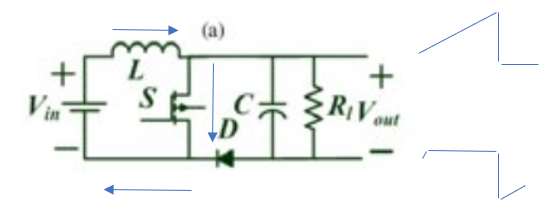
Powering up when the switch is open, the capacitance is being charged through the inductor. The positive voltage (V+) ramps upward while the load's return rises to one diode drop above ground: enter image description here

Now the switch closes, pulling the right side of the inductor and the top of the capacitor to ground. V+ is pulled to ground and stays there while the switch is closed. V minus goes sharply negative, but then slowly increases as the load resistance discharges the capacitor:enter image description here

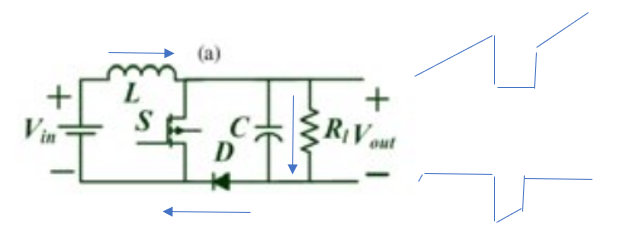
The switch opens again, and the inductor voltage jumps positive. The capacitor and resistor are floating since the diode is back biased. They also jump with the inductor voltage until the low side of the capacitor is one diode drop above ground. Then the diode starts to conduct, and the capacitor is further charged from the inductor current:enter image description here

Finally, the switch closes again, pulling the high side of the capacitor to ground and driving the low side of the capacitor even more negative, which is once again discharged by the resistor:enter image description here

And so on. Eventually for a given duty cycle, the capacitor will be charged and discharged by the same amount. One side of the load will be bouncing above the power supply and the other slightly above and below ground, but from a differential (ideal) standpoint it looks like any boost converter. I have no idea why anyone would do this. Maybe a reader can suggest something?

So I would say it is floating but there are whitecaps on the sea.

\$\endgroup\$
1
\$\begingroup\$

To answer your first question, no. Unless the input ground is floating as well, none of your examples are 'floating' converters in the scope of the circuit, and neither is it isolated(both ends have an electrical connection to each other). A 'floated' output is regarded as when the output ground is not connected to the input ground, and is completely isolated(i.e. no electrical connection) from the input side.

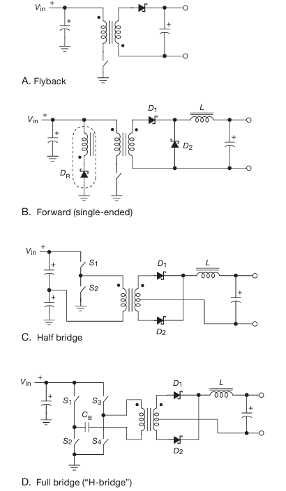
To answer your second question, only a transformer provides isolation while transferring power, however this does not work with pure DC(unless the DC power is being repeatedly switched, like in a flyback converter). Flyback converters can be made as DC-DC isolated converters, like this example from the Art of Electronics(3rd edition, page 655 on physical copy, 85 on PDF).

enter image description here

All of these converters are isolated, as there is no physical connection between Vin and Vout. The output is also floating(with figures C and D), with Vout ground being connected to the centre tap of the transformer(zero potential). A floating output is defined as where the output ground is not connected in any way to another ground(i.e. earth). Put simply, it is literally a point where there is zero potential flowing, and serves as a normal ground.

\$\endgroup\$
1
\$\begingroup\$

I think this is a case of prescriptive vs. descriptive error.

The language barrier doesn't help, either -- perhaps the authors themselves (or who/what ever translated the paper) don't quite understand the meaning, or it was a poor choice of words. It takes two to communicate, after all, and fault can lie with either party, or both. And I mean, language is hard -- it's no accident that it's a common problem.

There are downsides to these free-publication-access services; I don't mean in terms of the service itself (i.e. ResearchGate or etc.), but in terms of the quantity and quality of publications that turn up on web searches. At least in my experience, many of them are from eastern universities, with poor quality academic programs, and I've seen several instances of unchecked plagiarism myself. Unclear language is par for the course; many of the journals searched/archived by these services are low-quality themselves, have lax editorial standards, or are even pay-to-publish. So -- as is always the case, and always has been -- we must consider these sources critically, not take them too seriously, but check out and evaluate statements they make, cross-check them as we go, and build up a web of confidence that supports their statements and connects them with other known and understood (to ourselves) topics. It is an onerous process, reviewing documents, but it is one that is less and less provided to us by readily-available resources, so we are left to do it ourselves.

Anyway, the gap I think is interpreting it as descriptive (the output is floating --> in what way is it floating, if there is clearly a connection to the other side?!), when the intended meaning was prescriptive (the load must be floating). It's a useful distinction, there are many simplifications we can perform on a basic converter when the load is floating -- an LED buck supply for example might have a high-side load and low-side (peak) current sense -- but if we are not allowed to make them (because the load is restricted to common-ground or common-supply connection), then we have to do the full design, and perhaps incur the cost of some level translators, current or voltage sensors, etc..

And, we could always use an isolated-type converter even when not necessary, but isolated converters incur costs (design complexity, more materials, space) that non-isolated types do not, so as long as those are design pressures for a given project, non-isolated types will always be a consideration. (That's probably pretty obvious or self-evident, but, just to round out the point.)

\$\endgroup\$

Your Answer

By clicking “Post Your Answer”, you agree to our terms of service and acknowledge you have read our privacy policy.

Not the answer you're looking for? Browse other questions tagged or ask your own question.