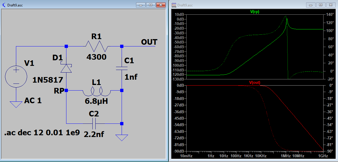
Regarding your question title, this circuit is commonly known as a "crystal radio receiver". The name comes from the original rectifier components -- actual crystals -- that have been replaced by silicon diodes in modern versions. This name is still commonly used, though.
It is a type of AM detector. The theory of operation is that a tuned circuit, usually some variant of an LC "tank circuit" consisting of an inductor and capacitor in parallel, is made to resonate at a target RF frequency, where the amplitude of the frequency corresponds to the encoded audio signal (i.e., AM or "amplitude modulation"). The voltage across the tank circuit averages zero -- it carries both the positive and negative voltage peaks of the RF signal. The rectifier passes only the positive half of the RF signal on to the rest of the circuit, and so the average voltage passed by the rectifier is proportional to the amplitude. A low-pass filter can be used to "average out" the RF, passing the amplitude modulated audio signal. The low-pass filter can be an explicit RC circuit, or -- as is the case in the simplest version -- a side effect of the physical characteristics of a ceramic earphone.
As I mentioned in a comment, your version of this circuit is a little weird. If the antenna was connected at the alternate point (the other side of the diode), it would be a traditional crystal radio circuit. The signal from the antenna and ground would be applied across the L1/C2 tank circuit, the diode would rectify the RF signal, and the R1/C1 low-pass filter would pass the audio to "OUT". (I'm not surprised your circuit still works as shown, and the principles of operation are going to be more or less the same.)
With respect to your LTspice simulation of this circuit, you can't model the antenna input as a plain voltage source. See this answer for example. In your circuit, if V1 is just a pure RF voltage source, then D1, L1, and C2 aren't doing anything. They are just a bunch of components connected between V1 and ground, and might as well be in the next room. All you're modeling is a radio frequency input V1 connected to R1 and C1, which form an audio frequency RC low pass filter, and that's why there's nothing interesting at OUT.
(The reason @VoltageSpike gets useful plots is that they're looking at RP which is in the middle of the network of otherwise useless components.)
The simple solution here is to model your antenna as V1 in series with a small capacitance -- the above-linked answer suggests 160pf (1000 ohm impedence at 1MHz) -- and you should get some more reasonable output. The peak resonance will match the peak resonance observed by @VoltageSpike, for the reasons below.
You don't need to simulate this circuit to figure out what's it tuned to, though. The primary resonant component here is the LC "tank" circuit, consisting of L1 and C2 in parallel. It has a peak resonant frequency given by f(Hz) = 1/(2 pi sqrt(LC)), which works out to around 1300kHz for the L1 and C2 values you've listed. I wouldn't take this too seriously though. Unless you used high precision components, the actual values of L1 and C2 are probably only within 10-20% of their nominal values anyway.
As long as the station is strong enough and you've got enough antenna, you ought to be able to pick up anything from 1200-1400kHz or maybe even a wider range. Note that adding another 2.2nF in parallel with C2 will tune down to 920kHz, so that might be an option if you have something down there. (This is all assuming that you don't want to try to incorporate a variable capacitor, which would allow you to tune more carefully.)
The key to getting these circuits working, especially when you can't tune them perfectly, is a big enough antenna and a good enough ground. A person only makes a so-so antenna. If there's a really strong radio station nearby, you might pick it up. If not, a couple dozen feet of copper wire strung across the ceiling will work better. Also, the ground you describe might not be adequate. You're relying on the amplifier ground, so you're relying on the power supply ground, but what ground is that? If you're using a two-prong wall wart, the output ground is very likely going to be isolated from the AC neutral through the switching transformer for safety reasons. Since this isolation isn't intended to isolate RF, you might get some effective grounding at RF frequencies, but it's hard to say.
Consider attaching a "real" ground directly to the LC tank. Traditionally for old crystal sets, you either ran the wire out the window and into a ground rod, or you at least alligator clipped it to all metal plumbing. If you're worried about ground loops, you might be able to put the RF ground in series with a midsized bypass capacitor, say 0.1uF. If you're in a location where it's not practical to connect a real ground, a long piece of wire strung along the ground could work well, too.


