0
\$\begingroup\$

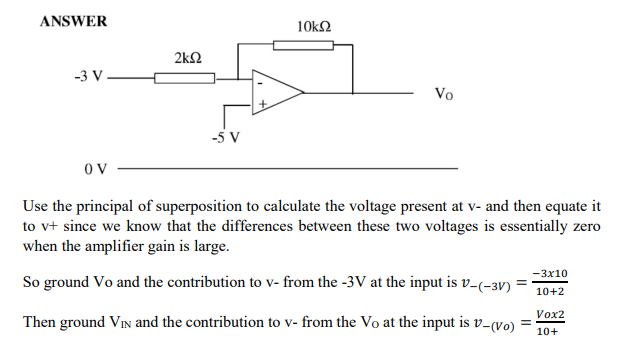
I was wondering if there is a single formula that expresses the voltage to the inputs of an op-amp, lets say an inverting op-amp, in every case?

In the example attached, I understand how the contribution from \$ V_o\$ : \$ \frac{R_1}{R_1+R_f} \cdot V_o \$ as it is just the output voltage multiplied by the feedback. But why is the contribution from \$V_{in}\$ : \$ V_{in} \cdot \frac{R_f}{R_1 + R_f} \$? Why is it not just \$-3V\$? Is there a general formula that states:

\$V_- = V_{0} \cdot \frac{R1}{R1+Rf} + V_{in} \cdot \frac{Rf}{R1+Rf} \$

I understand that it may be on an example to example basis, but I am struggling to understand how you deduce which resistor you are meant to look at.

Example Inverting Op-Amp

\$\endgroup\$
4
  • \$\begingroup\$ The answer is actually calculating the transfer function from one node to another. The transfer function from Vin to V- is Rf/(Rf+R1) in this case, but there' no general formula describing this - it all depends on the topology. \$\endgroup\$
    – Jack Black
    Commented Apr 28 at 15:18
  • \$\begingroup\$ In the formulas above, swap Vo and Vin. \$\endgroup\$ Commented Apr 28 at 23:34
  • \$\begingroup\$ "I am struggling to understand how you deduce which voltage divider you are meant to look at." – I'm not sure what you mean by this. It looks to me like the circuit you posted has exactly one voltage divider, and the one you're meant to look at is that one. \$\endgroup\$ Commented Apr 29 at 10:57
  • \$\begingroup\$ @TannerSwett Sorry the question is poorly worded. I just meant how you know if you are interested in the voltage across R1 or Rf. I understand now that the voltage dropped across Rf is the contribution from Vin, and vice versa for V0. :) \$\endgroup\$
    – 5eamus
    Commented Apr 29 at 20:54

4 Answers 4

1
\$\begingroup\$

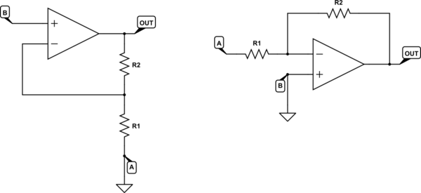
I'm not sure if this is the kind of thing you are asking for, but it might help. For the following arrangement, there is a general formula for the relationship between \$V_{OUT}\$, \$V_A\$ and \$V_B\$:

schematic

simulate this circuit – Schematic created using CircuitLab

$$ V_{OUT} = V_B\left( 1 + \frac{R_2}{R_1} \right) - V_A\frac{R_2}{R_1} $$

This can be interpreted to mean that any variation in \$V_B\$ (while \$V_A\$ remains constant) will be subject to gain \$1+\frac{R_2}{R_1}\$, and any variation in \$V_A\$ (while \$V_B\$ is fixed) will be subject to gain \$-\frac{R_2}{R_1}\$.

By setting \$V_A\$ to zero, or \$V_B\$ to zero, effectively you are producing the following two configurations respectively:
schematic

simulate this circuit

No doubt you recognise these as classic non-inverting and inverting amplifiers, and you can see by plugging in \$V_A=0\$ and \$V_B=0\$ into the above general equation, you obtain their well-known gain equations.

On the left, with \$V_A = 0\$ we have the non-inverting relationship:

$$ \frac{V_{OUT}}{V_{B}} = 1 + \frac{R_2}{R_1} $$

On the right, inverting, when \$V_B = 0\$ we have:

$$ \frac{V_{OUT}}{V_{A}} = -\frac{R_2}{R_1} $$


If you are comfortable with the concept of negative feedback (via the potential divider formed by R1 and R2) causing the op-amp to produce whatever output is necessary to equalise its two inputs, then the general formula (the first equation I wrote above) is easy to derive. Consider this:

schematic

simulate this circuit

The op-amp's inverting input potential is \$V_Q\$, and its non-inverting input has potential \$V_B\$. From op-amp behavior with negative feedback, we can state:

$$ V_Q = V_B $$

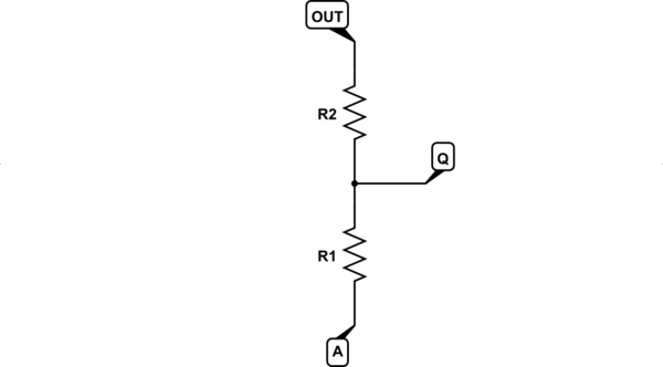
\$V_Q\$ is some potential that lies between \$V_A\$ and \$V_{OUT}\$, as defined by the potential divider of R1 and R2. It might help to redraw that divider like this:
schematic

simulate this circuit

If you do the algebra you'll find:

$$ V_Q = V_A + (V_{OUT} - V_A)\frac{R_1}{R_1 + R_2} $$

From before, we stated that op-amp action with negative feedback will always cause \$V_Q\$ to settle at a value to equal \$V_B\$, so replace \$V_Q\$ with \$V_B\$:

$$ V_B = V_A + (V_{OUT} - V_A)\frac{R_1}{R_1 + R_2} $$

If you re-arrange that to make \$V_{OUT}\$ the subject, you will end up with the same general equation I started with:

$$ V_{OUT} = V_B\left( 1 + \frac{R_2}{R_1} \right) - V_A\frac{R_2}{R_1} $$

\$\endgroup\$
2
  • 1
    \$\begingroup\$ Wow thank you so much. Yeah this is a really clear example, going on my exam cheat sheet 100%. Definitely wish this is how it was explained in lectures, but becase Vb or Va are often grounded I understand why the shortcut is made. \$\endgroup\$
    – 5eamus
    Commented Apr 29 at 20:50
  • \$\begingroup\$ @5eamus I've wondered why it's not taught this way, too. Perhaps it is sometimes, I don't know, but I do get to "show off" my way here. This generalised approach is especially useful for systems with a single-ended power supply (instead of dual positive and negative supplies), where one of the inputs is biased at, say, half the supply potential, rather than zero. \$\endgroup\$ Commented Apr 30 at 2:04
1
\$\begingroup\$

There are a few simple rules, also called the golden rules of op-amps.

In general, in a properly working circuit with feedback, the inverting and non-inverting input voltages are equal, and no current flows in or out through the input pins.

That is enough to know before applying KCL or KVL to the rest of the circuit to come up with a formula for every op-amp circuit you encounter.

Even ones with capacitors or inductors as they all are just impedances and then you can find their transfer function even based on input frequency.

So, by applying the golden rules to your example circuit, if your V+ input is -5V, it means you don't even have to calculate anything to know the V- input will be -5V too, for example in a properly working inverting amplifier.

\$\endgroup\$
2
  • \$\begingroup\$ Sorry I cut the actual question out of the screenshot, but yes I used the rule that V_ = V+ = 5V. However this question asked you to find V0 which required you to find V_ so that you could equate it to 5V. Thank you for the advice on using KCL and KVL too :) \$\endgroup\$
    – 5eamus
    Commented Apr 28 at 16:08
  • 1
    \$\begingroup\$ It's -5V, and since you know all resistances and voltages and currents except Vo, the formula is really just applying Ohm's law to find what Vo matches what the current in resistors is. You don't need to find V- as it is V+ and V+ is known, so V- is too. \$\endgroup\$
    – Justme
    Commented Apr 28 at 17:02
0
\$\begingroup\$

Easily by applying Millmann Theorem at the inverting input : \$V_- = \frac{\frac{V_{in}}{R_1} + \frac{V_o}{R_f}}{\frac{1}{R_1}+\frac{1}{R_f}}\$ and another extra developping the expression you get the desired formula you stated.

why is the contribution from Vin: Vin * R1 / (R1 + Rf)? Why is it not just -3V?

I mean clearly there is a resistor R1 in front of the inverting input, so it takes a way a portion of the input voltage Vin, if it wasnt there yes it would be a -3V contribution from Vin

\$\endgroup\$
7
  • \$\begingroup\$ Thank you so much, this really helps. Yes, explaining it as the input resistor taking a portion of the input makes sense. As for Millmann Theorem, I'll write that one down, not something I've seen in class before. Does it just apply to inverting amplifiers? \$\endgroup\$
    – 5eamus
    Commented Apr 28 at 15:16
  • \$\begingroup\$ en.wikipedia.org/wiki/Millman%27s_theorem have fun reading this \$\endgroup\$ Commented Apr 28 at 15:24
  • 1
    \$\begingroup\$ It would really make my day if you tell me about them ! @Circuitfantasist \$\endgroup\$ Commented Apr 29 at 10:25
  • 1
    \$\begingroup\$ @Circuitfantasist Thank you so much kinda sir Mechkov, im really interested in the writeup in your website, too much interesting information never paid attention to! \$\endgroup\$ Commented Apr 29 at 16:52
  • 1
    \$\begingroup\$ @Knowledge Seeker, It turns out that just a month ago I developed such a detailed answer about the “philosophy” behind the two basic op-amp configurations with negative feedback. If I think of anything else, I will add it here. I would be happy if you could comment on what I have written. Once again, thank you for your responsiveness! \$\endgroup\$ Commented Apr 29 at 18:23
0
\$\begingroup\$

But why is the contribution from \$V_{in}\$ : \$ V_{in} \cdot \frac{R1}{R1 + Rf} \$? Why is it not just \$-3V\$?

First to note that the expression is not \$ V_{in} \cdot \frac{R1}{R1 + Rf} \$ but \$ V_{in} \cdot \frac{Rf}{R1 + Rf} \$.

The input voltage Vin = -3 V cannot be directly applied to the inverting input since it will override the output voltage Vo acting through the resistor Rf. Vin must act through another resistor (R1). Thus the two resistors R1 and Rf constitute a resistor summer with weighted inputs. Their "gains" are Gin = Rf/(R1 + Rf) for the circuit input and Gout = R1/(R1 + Rf) for the op-amp output. So the voltage of the summing point (op-amp inverting input) is V- = Gin.Vin - Gout.Vout. If the input voltage would be directly applied (R1 = 0), then Gin = 1 and Gout = 0, so V- = Vin.

See more about the “philosophy” behind the two basic op-amp configurations with negative feedback in another answer of mine.

\$\endgroup\$

Your Answer

By clicking “Post Your Answer”, you agree to our terms of service and acknowledge you have read our privacy policy.

Not the answer you're looking for? Browse other questions tagged or ask your own question.