0
\$\begingroup\$

I calculated Vo for this ideal op amp circuit using the formula: \$R_2\$/\$R_1\$(\$V_2\$-\$V_1\$) = \$V_o\$
I believe the correct \$V_o\$ = -14V I did not get this result using the above formula. It seems the formula is not correct for this circuit but I don't understand why. Would someone please enlighten me?

schematic

simulate this circuit – Schematic created using CircuitLab

\$\endgroup\$
2
  • 2
    \$\begingroup\$ (1) You are using a wrong equation for the output voltage. Notice that that this is not a differential OpAmp topology. To derive a correct formula, use the Kirchhoff's Current Law. (2) The rest of the enlightenment is in your own hands. After all, this is a homework. \$\endgroup\$ Commented Mar 12, 2016 at 5:13
  • \$\begingroup\$ Daveythewavey, ask yourself for which reason you wanted to use the mentioned formula? Did you derive it? No. So - where does it come from? \$\endgroup\$
    – LvW
    Commented Mar 12, 2016 at 9:39

3 Answers 3

2
\$\begingroup\$

It seems the formula is not correct for this circuit but I don't understand why

That's not a differential amplifier.

To solve that circuit you can proceed in at least two ways (assuming ideal op-amp). Here are a few hints (you won't get the full solution):

  1. Superposition. Null the two independent sources \$V_1\$ and \$V_2\$ one at a time, and then sum the two partial responses. By nulling \$V_2\$ you're left with an inverting amplifier; by nulling \$V_1\$, with a non-inverting amplifier.
  2. Impose ideal op-amp conditions. Recall that an ideal op amp, when there is a feedback path from the output to the input, adjusts its output to have $$v_\mathrm{n}=v_\mathrm{p},$$ where \$v_\mathrm{n}\$ is the potential of the inverting input and \$v_\mathrm{p}\$ that of the non-inverting one. In your circuit, this implies \$v_\mathrm{n} = V_2\$. Knowing this, you can easily apply Millman's theorem at the inverting input (or Kirchhoff's laws, if you feel more comfortable), considering the circuit containing the sources \$V_1\$ and \$v_\mathrm{o}\$. Then solve for \$v_\mathrm{o}\$.
\$\endgroup\$
1
\$\begingroup\$

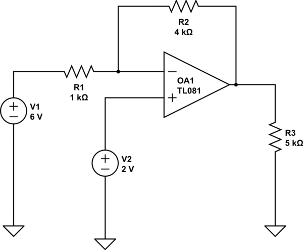
schematic

simulate this circuit – Schematic created using CircuitLab

Figure 1. Inverting op-amp with offset on non-inverting input.

  • The trick here is to remember that the op-amp doesn't know where your GROUND or 0 V is. This should be obvious from the schematic as there is no 0 V connection to the op-amp.
  • In the inverting amplifier configuration the op-amp will try to adjust the output until the inverting input voltage is the same as the non-inverting input. This will happen when both are at +2 V above ground and your effective input is 4 V relative to the non-inverting input. -The gain of the circuit will be \$-\frac {R_F}{R_I} = -4\$ relative to the non-inverting input so

$$ V_{OUT} = -(V_1 - V_2)\frac{R_F}{R_I} + V_2 = (6-2)\frac{-4}{1} + 2 = -14 V$$

I did not get this result using the above formula.

In a practical experiment you might not get 14 V out. If this is the case you are probably driving the op-amp too close to the negative power rail. You have to either increase the negative power-rail voltage (watch the specifications) or decrease your 6 V input signal.
\$\endgroup\$
5
  • \$\begingroup\$ transistor: you speak about "the gain". Which gain are you referring to? Vout/V1 or Vout/V2? I rather think, it is a simple case for superposition of TWO output values caused by TWO gain values. The formula in the question is NOT correct because it gives 4*(2-6)=-16V. \$\endgroup\$
    – LvW
    Commented Mar 12, 2016 at 12:38
  • \$\begingroup\$ You're right. I misunderstood some of his statements. Does it look right now? \$\endgroup\$
    – Transistor
    Commented Mar 12, 2016 at 12:47
  • \$\begingroup\$ The result is OK, of course. However, where is the logic behind the calculation? Here is my approach: Vout1=-4*6=-24V and Vout2=2*(1+4)=+10V. Hence, Vout=-24+10=-14V. \$\endgroup\$
    – LvW
    Commented Mar 12, 2016 at 16:30
  • \$\begingroup\$ Yes, considering the output as the sum of an inverting amplifier and a non-inverting amplifier is a good method. The logic of my method is to take the non-inverting input as reference, calculate the output relative to that and then add in the non-inverting input voltage as an output offset. \$\endgroup\$
    – Transistor
    Commented Mar 12, 2016 at 17:17
  • \$\begingroup\$ I like your method: it's elegant and fast, and would be my favourite in many situations: however, I suspect it's not easily understood by students because it requires a deeper level of understanding about the op amp (frequently, students have difficulties in understanding that the op amp doesn't know where the ground is). \$\endgroup\$ Commented Mar 12, 2016 at 19:41
0
\$\begingroup\$

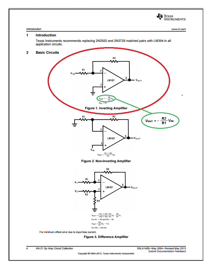
From TI/NSC:

enter image description here

Or...

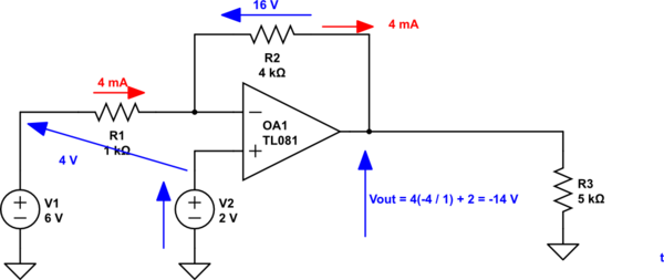
  1. because of the way opamps work, the voltage on OA1- must be equal to, and the same sign as, the voltage on OA1+
  2. If OA1+ is at +2V, then OA1- must also be at +2V.
  3. If OA1- is at +2V then R1 has 4 volts across it.
  4. If R1 has 4V across it then the current through it must be \$ I =\frac{4V}{1000\Omega} = 0.004 A \$
  5. Since R1 and R2 are in series, the current through R2 is the same current through R1.
  6. Since R2 is 4000 ohms and there's 0.004 A through it, it must be dropping \$ 0/004A \times 4000 ohms = 16 \text{ volts.}\$
  7. Since OA1 is an inverting amplifier and OA1- is positive, OA1 OUT must be negative.
  8. Since the voltage on the left-hand side of R1 is +2 volts, the total drop across R2 is 16 volts, and OA1 OUT must be negative, OA1 OUT must be at -14 volts.
  9. R3 doesn't matter since it's not in the loop.
\$\endgroup\$

Your Answer

By clicking “Post Your Answer”, you agree to our terms of service and acknowledge you have read our privacy policy.

Not the answer you're looking for? Browse other questions tagged or ask your own question.