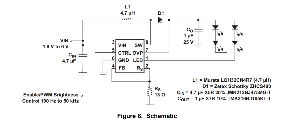
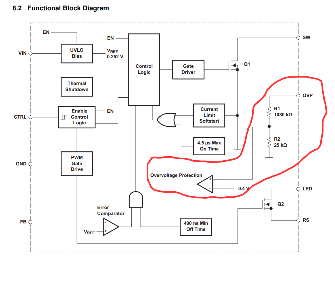
Current regulators work by monitoring current flow, and constantly raising or lowering their output voltage until the desired target current is achieved. These adjustments happen very quickly, and the output settles at an appropriate voltage almost instantly. Because they are measuring current, they do not need to know anything about their load. They do not need to be told what the target voltage is, the current source will find that value itself, by trial and error, using a negative feedback in a closed control loop. The rest of this answer explains these concepts in more detail.
An LED (or any two-terminal device) has some relationship between the current flowing through it, and the voltage appearing across it. You can specify (set) the voltage across it, and monitor what happens to current through it, or you can alter the current through it, and see how the voltage across it changes in response.
Below is an LED being powered by a current source (left), and the same LED being powered from a voltage source (right). The main point to note is that in both cases, the LED will pass the same current, and develop the same voltage, even though we are controlling voltage in one and current in the other:
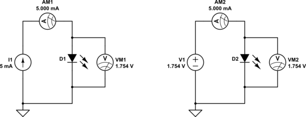
simulate this circuit – Schematic created using CircuitLab
In the following two graphs, the first one shows how LED voltage varies when I explicitly "push" more and more current through it, and the second shows variation of LED current as I raise the voltage applied across it:
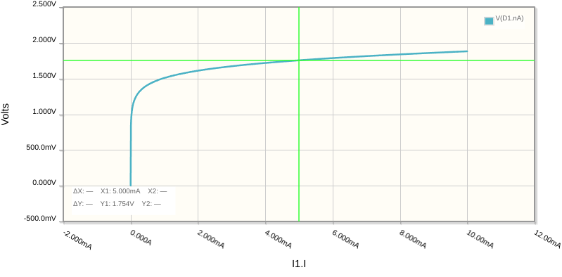
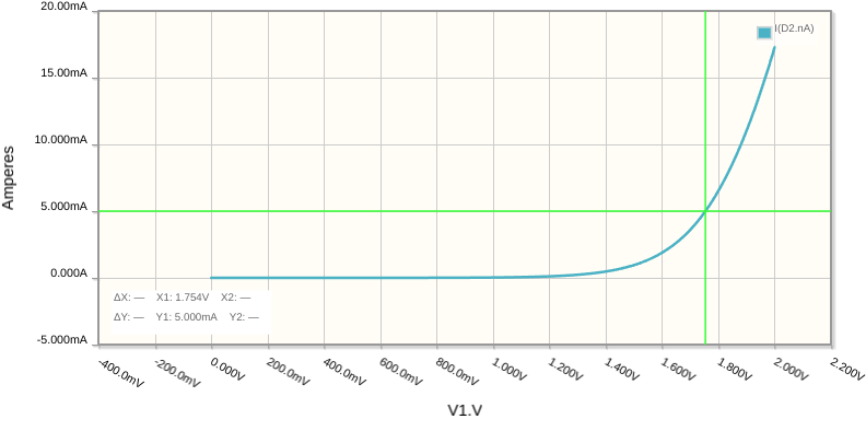
You can see that it doesn't matter what current or voltage I impose, conditions are identical in both cases. In particular, the green markers show the voltmeter and ammeter readings from the schematic, 1.754V and 5mA in both cases, whether as a result of explicitly applying a potential difference of 1.754V, or explicitly pushing 5mA through it.
The second point to take away here is that you may consider a current source to be an adjustable voltage source, that will produce whatever voltage is necessary to cause the load to pass exactly some desired current. In other words, it raises or lowers the voltage across it, forever adjusting that voltage, until the exact, required current is flowing.
This last description of a current source is what you are asking about: how does a current source know when to stop "raising" or "lowering" its voltage, to settle at exactly the correct voltage to pass, say, 5mA?
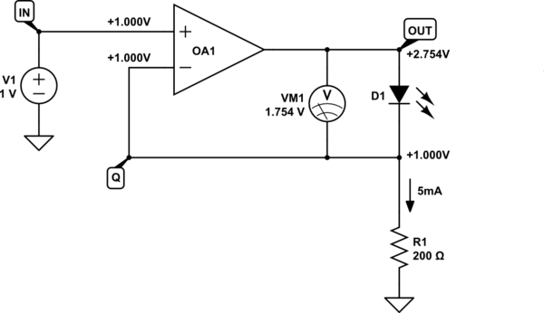
The solution is to measure current somehow, and adjust voltage across the LED until the target current is achieved. This can be performed in a number of ways. I will illustrate one such way, employing a resistor to measure current, and an op-amp with negative feedback to adjust voltage:
simulate this circuit
With negative feedback, an op-amp will equalise the potentials of its two inputs (inverting and non-inverting). By applying exactly \$V_{IN}=+1V\$ to the non-inverting input, I am telling the op-amp to produce whatever output potential \$V_{OUT}\$ is necessary to produce exactly \$V_Q=+1V\$ at Q, its other, inverting input. To do this, the op-amp must either raise or lower its output potential \$V_{OUT}\$.
Also, we can say that when this condition is reached, and \$V_Q=1V\$, then there will be 1V across resistor R1, and Ohm's law tells us the current that will be flowing:
$$ I = \frac{V_Q}{R_1} = \frac{1V}{200\Omega} = 5mA $$
In other words, by choosing \$R_1=200\Omega\$, and \$V_{IN}=1V\$, I am setting the conditions that must prevail, 5mA will be flowing.
If less than 5mA is flowing through R1, the voltage across the resistor will be less than 1V. In such circumstances, the op-amp must raise it's output, to increase \$V_Q\$. If more than 5mA is flowing, then \$V_Q\$ will exceed 1V, and the op-amp must lower \$V_{OUT}\$, in turn lowering \$V_Q\$.
The op-amp output must settle at the condition \$V_Q=V_{IN}=+1V\$, at which point (as we calculated above) current will be \$I=5mA\$. The schematic above shows this state, and you will notice that the voltage developed across the LED (shown on voltmeter VM1) is exactly what we predicted it should be: 1.754V. And yet we never told the system explicitly to produce 1.754V across the LED. We have permitted the LED to decide for itself what its voltage should be.
All we did was tell the op-amp what voltage (1V) to "aim for" across R1 (200Ω), and the result is that the op-amp, through trial and error, found that this condition is satisifed when \$V_{OUT}=+2.754V\$.
We have built a current source of 5mA. It is an adjustable voltage source, able to shift its output voltage up or down until the condition \$I=5mA\$ is met, which is exactly the description of a current source I wrote earlier.
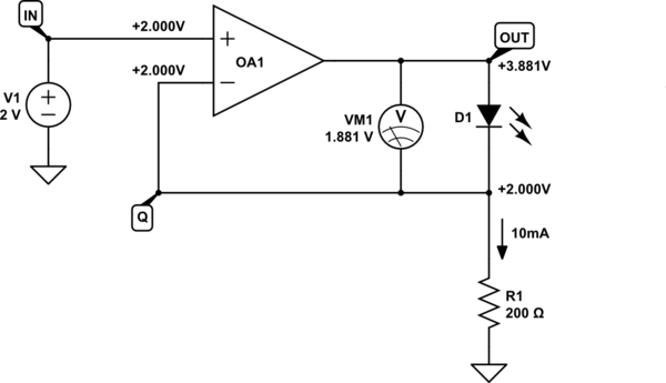
You may change \$V_{IN}\$ or \$R_1\$ to set the target current. For instance, if I set \$V_{IN}=+2V\$, then \$V_Q\$ will also settle at +2V, and the current through R1 (and the LED) will be:
$$ \frac{V_{IN}}{R_1} = \frac{2V}{200\Omega} = 10mA $$
simulate this circuit
When 10mA passes through this LED, the voltage across it will no longer be 1.754V, which we can see from the graphs above. Now that voltage is 1.881V, but we never had to tell the circuit to aim for 1.881V across the LED. All we did is set target current to 10mA, and the diode again decided its own voltage. The op-amp then "found" the condition \$V_{OUT}=+3.881V\$ necessary to pass 10mA of current.
The above circuit is a very simple demonstration of current regulation, but it's not good for currents over 10mA or so. There are other ways to obtain higher currents, usually involving inductors and transformers, or beefy transistors, but the principle remains the same: An op-amp is used in a closed-loop, to measure current, and adjust the voltage across the load until some target current is flowing. In all cases, the load's voltage (under the condition where the exact required current is flowing) need not be known by the system. The closed-loop system is simply aiming for some target current to flow, and will produce whatever voltage is required for that to happen.


