0
\$\begingroup\$

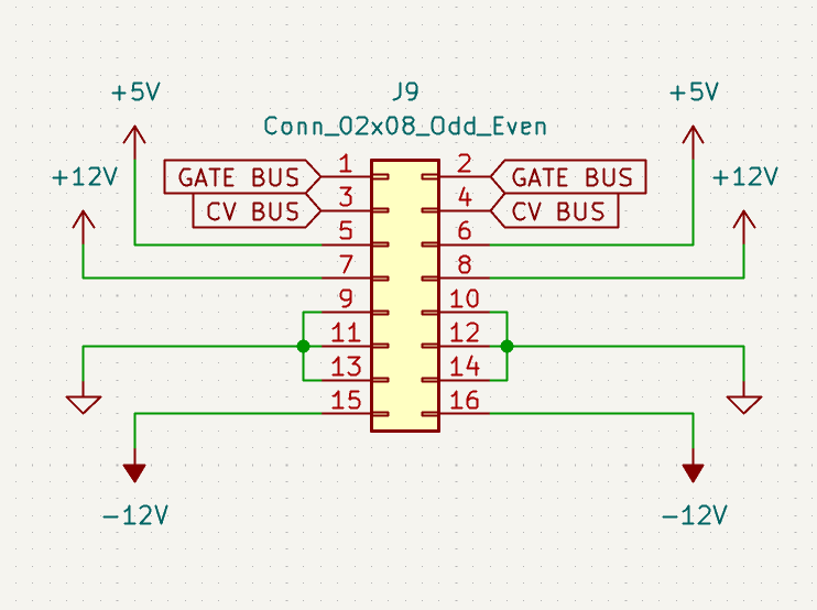
I have a pair of +10.5V and -10.5V linear regulators (XC6216DA52PR-G and XC6902NA51PR-G respectively, both in the SOT-89 package) wired up as shown in the first schematic. The input power is from a dual +/-12V supply provided via a 16 pin IDE connector, the wiring of which is shown below in the second schematic.

I have an issue where my entire circuit powers up fine when the IDE connector is plugged in directly downwards connecting both +12V and -12V pins simultaneously, or when one side is seated first such that +12V is connected, followed by GND, followed by -12V. However, if the IDE connector is connected such that -12V is connected first, then GND, then +12V, the -10.5V regulator comes up fine and I see -10.5V on its output pin, but the +10.5V fails to come on and only outputs 0V on the output pin.

Is there a way to resolve this problem so that both power regulators come on regardless of which order the pins in the power connector come into contact?

I did try it again without the reverse current protection mosfets and experienced the same issue.

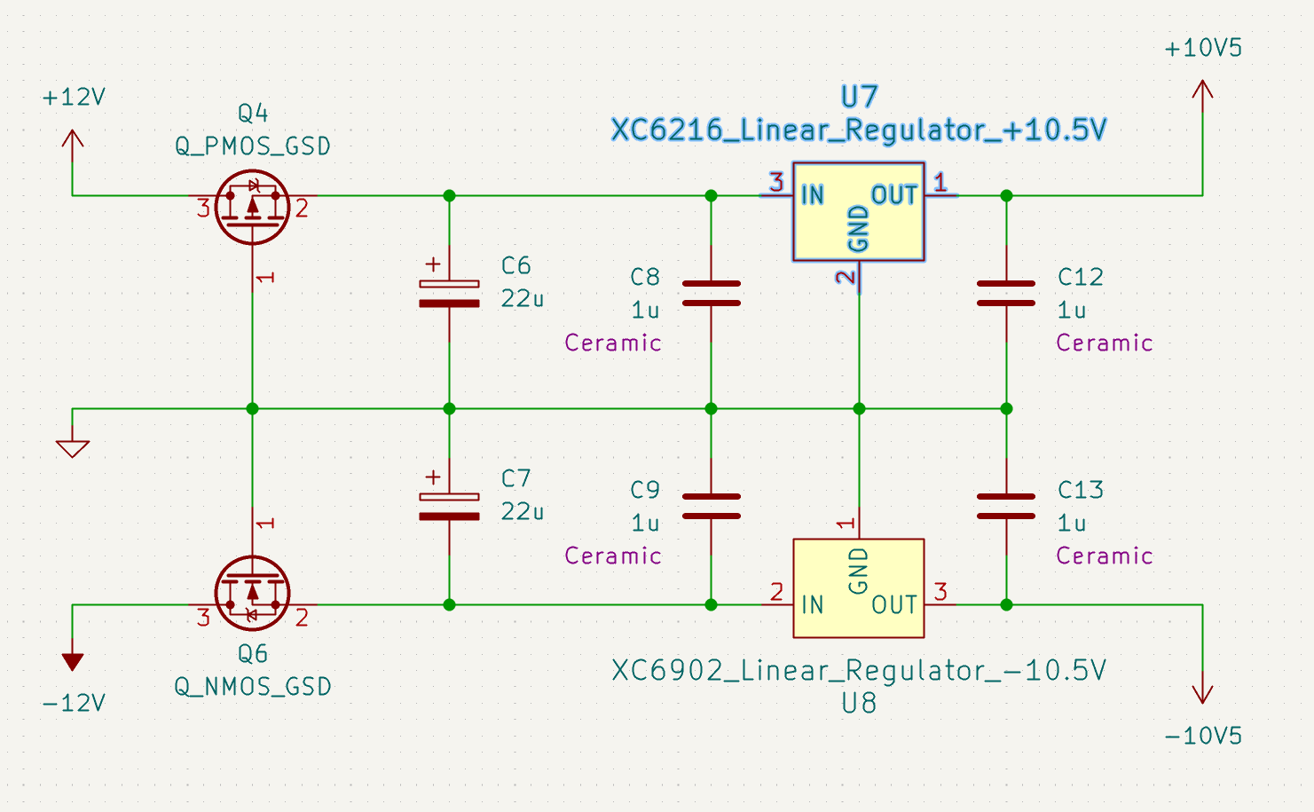
Schematic showing linear regulator wiring

Schematic showing power connector wiring

\$\endgroup\$
6
  • 2
    \$\begingroup\$ This is likely not a problem with the regulators themselves, but rather with the load connected to them. It draws too much current to allow the positive regulator to start up properly when the negative one comes up first. So... What's the load? How's it connected to the power rails? \$\endgroup\$ Commented May 17 at 0:44
  • \$\begingroup\$ @JonathanS. Thanks, that's an interesting hypothesis. The load is an analog synthesizer oscillator circuit composed of many TL074 op amp chips. I'm not sure if they are behaving strangely when the -10.5V rail comes online before the +10.5V rail does. The overall schematic is large so I might see if I can reproduce the issue with a minimal setup first. \$\endgroup\$
    – Jordan M
    Commented May 17 at 0:53
  • 1
    \$\begingroup\$ In general, hotplugging an IDC connector like this one is an invitation for trouble - imagine what'll happen when -12V and +5V come up first (before ground). Your +5V could become +10V for a moment (relative to the floating ground) and fry everything connected to it. You need at least some way to ensure that ground always connects first. \$\endgroup\$ Commented May 17 at 1:01
  • \$\begingroup\$ @JonathanS. That would be a great idea. Unfortunately this interface is a de-facto standard for Eurorack synthesizer modules, so I can't make modifications to it without sacrificing compatibility. I think the answer may probably be to always ensure the power is off before connecting anything, unless there might be a way to block the both the power rails before ground is connected (I would like to protect the end product against abuse if possible) \$\endgroup\$
    – Jordan M
    Commented May 17 at 1:11
  • \$\begingroup\$ What is the design intent for Q4 and Q6? \$\endgroup\$
    – AnalogKid
    Commented May 17 at 1:57

1 Answer 1

2
\$\begingroup\$

Try connecting a reverse-biased Schottky diode such as 1N5819 across each regulator output.

\$\endgroup\$
5
  • \$\begingroup\$ That seems to fix it! Is this protecting the voltage regulators from a situation where ground goes above the output? Is there a reason for choosing a Schottky over another type of diode? \$\endgroup\$
    – Jordan M
    Commented May 17 at 3:06
  • \$\begingroup\$ To clarify, I connected the diodes between the regulator outputs and ground. It takes a moment for the regulator to power up but it does come online every time now. When the power is connected to all pins simultaneously, the regulators come on instantly. \$\endgroup\$
    – Jordan M
    Commented May 17 at 3:13
  • 1
    \$\begingroup\$ @JordanMelo Schottky diodes have a lower voltage drop when forward biased - around 0.2V, rather than 0.6V. In this case, that means better protection to the regulator. \$\endgroup\$
    – Simon B
    Commented May 17 at 9:05
  • 1
    \$\begingroup\$ During startup the load can pull the positive regulator output below ground or the negative regulator output above ground, forward-biasing internal junctions and causing behaviour that may be undesirable. Using a relatively beefy (1A) Schottky diode ensures that most of the reverse current flows through the external diode and not through internal (P-N) junctions. \$\endgroup\$ Commented May 17 at 15:06
  • 1
    \$\begingroup\$ @SpehroPefhany Thank you for the more detailed explanation and design rationale! \$\endgroup\$
    – Jordan M
    Commented May 17 at 22:34

Your Answer

By clicking “Post Your Answer”, you agree to our terms of service and acknowledge you have read our privacy policy.

Not the answer you're looking for? Browse other questions tagged or ask your own question.