2
\$\begingroup\$

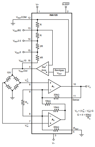
I am using a INA125 to amplify the signal from a load cell. When I connect everything according to the datasheet as seen below, the reference voltage drops when I connect the load cell. I am supplying the IC with 24 V and 0 V.

If I measure the output voltage when nothing is connected it reads 10 V. When I connect the load cell it drops to 6.8 V. the two signal leads are 3.4 V as expected.

I am thinking that the INA125 can not supply enough current but I cant find the limits in the datasheet.

Can somebody give me any advice on how to solve this? Maybe adding the transistor will help?

Thank you very much!

enter image description here

Datasheet: https://www.ti.com/lit/ds/symlink/ina125.pdf)

\$\endgroup\$
6
  • \$\begingroup\$ what is the resistance of your load cell? \$\endgroup\$ Commented May 22 at 10:08
  • \$\begingroup\$ Reference current is +/- 8 mA ... \$\endgroup\$
    – Antonio51
    Commented May 22 at 10:28
  • 3
    \$\begingroup\$ Consider using the current boost circuit described in fig 4 on page 12. \$\endgroup\$
    – brhans
    Commented May 22 at 10:35
  • \$\begingroup\$ The resistance over the two excitation leads is about 330 ohm. where did you find that Antonio51? \$\endgroup\$
    – tijnvr
    Commented May 22 at 10:38
  • 1
    \$\begingroup\$ page 7, last figure "Vos" vs "Reference current". \$\endgroup\$
    – Antonio51
    Commented May 22 at 10:45

1 Answer 1

4
\$\begingroup\$

The reference is only characterized for 0-5mA output current. "IL = 0 to 5mA"- anything more than that is not guaranteed.

If you add the transistor there will be a few effects:

  1. The transistor needs about 0.7V to work, so the chip has to output a bit higher voltage. You need about 2V higher supply than the reference (1.25V from the datasheet plus 0.7V). A bit more if it has to operate in extreme cold conditions. 3V would be better. If you have a higher clean supply, you can connect that to the transistor collector. You have 24V, so no problem.

  2. The power dissipation associated with supplying the reference voltage to the bridge will mostly be moved to the transistor. So you may have to use a power transistor such as the TIP series rather than something like an SOT-23 part. Higher supply voltage relative to the output reference voltage means more dissipation, like any linear regulator. Eg. 50mA to the 10V bridge with a 24V supply would mean the transistor has to dissipate about 700mW.

  3. The current the chip has to be supplied will be reduced by the current gain of the transistor. The gain of the TIP29C will be at least 40 at 25°C, but could be 20 at -40°C. Even so you could get 100mA out of it.

  4. You forfeit any thermal protection or short-circuit current limiting that is built into the chip. If the user shorts the bridge the transistor power dissipation could be very high. You should consider adding a 'PTC' resettable fuse and calculating whether that will actually protect the transistor (it may need a much larger heat sink than that otherwise would be indicated).

The TIP31C has beta bins and the lowest one 'R' is pretty miserable (guaranteed gain of only 10 @ 25°C 1A and Vce = 4V, so it might only have a gain of 5 worst-case.. ugh). If you don't have a really horrible one, and don't store it in the freezer, it should work, however.

You need about 30mA with a 330Ω bridge. The transistor will be dissipating about 420mW so it will need to be something substantial. I would probably use something more modern like this TO-252 part with minimum gain of 500 @ 100mA.

It's good to physically separate the high power dissipation parts from the precision analog anyways to get better accuracy.

\$\endgroup\$
5
  • \$\begingroup\$ Can you say how the additional transostor will influence the noise figure? \$\endgroup\$
    – kruemi
    Commented May 22 at 13:00
  • 1
    \$\begingroup\$ I don't think it will have much effect as shown, assuming it remains stable. Almost all the noise is from the differential amplifier not from the excitation. They don't even spec the high frequency noise of the reference (low frequency noise is another matter, if the chip is dissipating all that power, the tempco is not insignificant, especially on the cheaper variants of the chip). That will be improved, probably quite noticeably, by adding the transistor & keeping it from heating the chip. It's also not guaranteed that internal heating will be as benign as changing the ambient temperature. \$\endgroup\$ Commented May 22 at 13:07
  • \$\begingroup\$ Though the dissipation should be pretty constant, so most of the ill effects would show up during warm-up rather than during normal operation. \$\endgroup\$ Commented May 22 at 13:10
  • \$\begingroup\$ @SpehroPefhany Thanks for the great answer, i also have a TIP120. this has a minimum gain of 1000, it seems great, almost to good to be true. what do you think? \$\endgroup\$
    – tijnvr
    Commented May 22 at 21:05
  • \$\begingroup\$ Sure. It’s a Darlington, hence the high gain, so it has a higher minimum drop, but you’ve got lots of voltage. \$\endgroup\$ Commented May 23 at 1:48

Your Answer

By clicking “Post Your Answer”, you agree to our terms of service and acknowledge you have read our privacy policy.

Not the answer you're looking for? Browse other questions tagged or ask your own question.