5
\$\begingroup\$

I've started a small project to renovate/rebuild an old record player for my wife. I have a degree in Electrical Engineering, but it's been almost 15 years since I last had to project/build a circuit, and it's been very fun revisiting my old books and fiddling with datasheets, KiCAD and LTspice. However, I'm writing this post to understand how would experienced engineers structure this solution. Here's what I know:

  • This record player is battery-powered with 9 V, so we're looking at a low-power +4.5 V / -4.5 V amp circuit, which should make some things easier w.r.t power driving and heat dissipation. It has a mono speaker, so I'm not too worried about stereo support either.
  • The record player's needle outputs audio at ~5 mV. I studied and tested a couple of RIAA preamps to balance the frequency response, so I know this will be a necessary block in the design. Most prebuilt designs I found are for 40 dB amps, bumping the output to ~500 mV.
  • However, the record player also has a built-in radio. The solution I've devised using an Si4824 outputs signal at ~75 mV.

Given the above information, I'd like to know what's the best way to design the amplification circuit for these two inputs. I have the following options:

  • Design a RIAA pre-amp for the record needle with a lower gain, matching the 75 mV output of the radio, and feed both to a common power amp circuit. This way I'd only have two circuits to design, but the RIAA pre-amp is a hard one due to the specific response curve.
  • Design a pre-amp for the radio, matching the 500 mV output of the ready-made RIAA pre-amps, and feed both to a common power amp circuit. This would require more components/board space (which I don't think is an issue), but would be easier to design, I think?
  • Design two totally separate circuits for each one. This can probably be the easiest part since I can probably make do with internet designs, but sounds like a waste. However, I'm not entirely sure how hard it is to design an amp circuit from zero, so maybe it's the best choice?

In your position, what would you do? And why? I'm curious to see how active engineers would tackle this decision.

\$\endgroup\$
1
  • 1
    \$\begingroup\$ Take a 40 dB amp, put a resistive divider after it, to attenuate a bit, so the signal after the attenuator matches the radio output. Then a single power amp. This will not be the lowest noise solution (due to the attenuator), but good enough and simplest \$\endgroup\$
    – tobalt
    Commented Jun 20 at 17:05

4 Answers 4

3
\$\begingroup\$

Given the fidelity of your signal sources, consider the LM386 or some other integrated audio power amplifier for the output stage. It runs on a single DC voltage. With a little attention to power supply decoupling, it saves a lot of effort.

Is your goal to build all circuits from scratch, or wire up pre-made modules? If the latter, ebay has a ton of options. I would go with the 40 dB RIAA preamp for the record, and a low-gain amplifier stage for the radio source. You easily can get a gain of 7 with one transistor. There are threads here and on other forums about the 1-transistor audio stage, how to bias it, etc, plus online calculators.

BJT Class A Amplifier - Help calculating resistor values \$R_C\$ and \$R_E\$

\$\endgroup\$
2
\$\begingroup\$

Any normal device would simply amplify (or attenuate if necessary) all sources to a common level before user volume controls and the speaker amp.

A record player would have a RIAA pre-amp with the curve and an output level to match the other possible sources. A tape player would also have a tape-specific preamp and output level set to something suitable. Then you just select which of the preamplified sources or line input RCA connectors are sent to the speaker amp.

\$\endgroup\$
2
  • \$\begingroup\$ Thanks for the input. I was able to adapt the gain of one of the RIAA pre-amp circuits I had available, and I'll proceed with this purpose. Time to dust off the A-class amp books now! \$\endgroup\$ Commented Jun 20 at 19:22
  • \$\begingroup\$ Changing the gain of an amplifier stage with three interacting time constants is not a straightforward thing. Please post your RIAA circuit. \$\endgroup\$
    – AnalogKid
    Commented Jun 21 at 4:33
2
\$\begingroup\$

I would start with the output requirements, the available power supply, the efficiency requirements, then go back towards the signal sources, as follows:

Step 1. What type of load are you driving, and to what power level?
For example: let's assume the output device (the one that makes the sound you hear) is a single 8Ω electro-dynamic speaker rated at 20W continuous. Do you want to drive it to its full power rating? If so, then you will need to drive its terminals to +/-18V peak (sinewave of 12.7Vrms).

However, if the load is a speaker enclosure rated overall 20W and it contains three electro-dynamic drivers (speakers) and a cross-over network, then the amplifier may need more power than the case of driving just one speaker coil. This is due to the cross-over network; it is not perfect at splitting the power evenly as required to all three speakers across the entire frequency range, plus it introduces its own distortions and EMC issues. For that reason, I would favour removing the passive cross-over, having a separate amplifier connected to each speaker (so three per speaker cabinet, six for a stereo system), and feeding each amplifier its own input from a small-signal frequency cross-over done using good-quality analog circuits and ICs.

Another example: your load may be a headset, rated 32Ω 0.2W. The power requirements for this are an order of magnitude lower than the previous example. Usually, I design for the worst-case (heaviest) load required, then introduce resistors at the output ports as required to reduce the maximum power delivery to the lighter loads just to ensure the beefy amplifier doesn't destroy the little load.

Step 2. Next, consider your power supply, and efficiency requirements. Why are they related? Well, suppose both of the following conditions are true:
(a) plenty of power available (at the correct voltage),
and
(b) plenty of room to mount good heatsinks on the amplifier.

In that case, both power efficiency and power dissipation are of no concern, so that allows you the freedom to select any one of the various classes of push-pull linear amplifiers to drive the load, eg: class A, B, or AB; of course, for low distortion and good sonic performance choose either class A, or class AB, for the latter the sonic performance may be improved by increasing the idle current at the expense of more standing power loss and increased heat load.

However, if either of these conditions are not true, then you may have to consider a more efficient amplifier class, such as Class D, G, or H. Class D involves very high-speed switching, and therefore is an order of magnitude more difficult to design than Class A, B, or AB; having said that, there do exist many chip-sets that do a good job of integrating much of the difficult stuff - but hey, where's the fun in that?

What is the output voltage of your power supply? For example, is it a 12V battery charger? In that case, the maximum output power an amplifier can deliver into an 8Ω load from this supply is very limited, particularly if the output is single-ended (one end of the load tied to 0V GND), simply because the voltage is so low - regardless of how much current the power supply can deliver. Your options to boost output power in this situation are:
A. Apply two amplifiers configured in a bridge, ie: drive both ends of the load; this can double the output voltage which increases the output power by a factor of 4 for a given load.
B. Include a power converter to boost the voltage rails to the amplifier.

Step 3. Now consider the input signal to your power amp. To be compatible with outputs from most modern-day (last 50 years!) audio equipment, choose either of the two main standards for line-level input: domestic (-10dBV, or 0.316Vrms, 0.89Vp-p), or professional (+4dBu, or 1.23Vrms, 3.47Vp-p). Or you can design for both, and have a selector switch or separate input jack.

Step 4. At the end of this process, your answer for what the output of each signal source should be is quite simple: it should match the input of the power amplifier, which is just the standard line-level you selected at step 3. You may need to attenuate or boost the output of the existing signal sources you now have to achieve that.

Further reading: This link gives some advice on designing a simple amplifier from common parts to deliver 1W into 8Ω at reasonable sonic quality from a 9V battery:

https://electronics.stackexchange.com/a/688822/341959

\$\endgroup\$
1
\$\begingroup\$

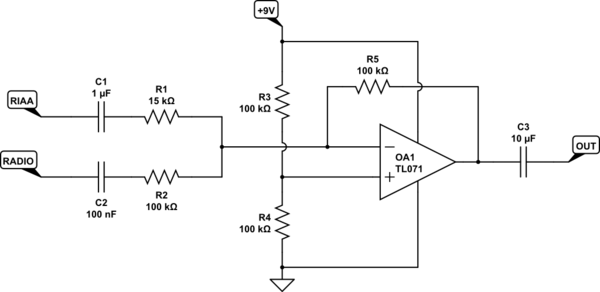
What about mixing the 75mV and 500mV signals into a single 500mV output:

schematic

simulate this circuit – Schematic created using CircuitLab

Gain is set to \$-\frac{R_5}{R_1}=-6.7\$ for the radio signal, and \$-\frac{R_5}{R_2}=-1\$ for the RIAA signal, so \$V_{OUT}=500mV_{RMS}\$ in both cases.

Since the radio and RIAA preamps have already taken care of the high-gain, low-noise requirements, such low gain in a subsequent stage like this can be implemented using almost any op-amp, with little concern for added noise.

The amplitudes of the inputs and output is well within the supply voltage, so you don't even need to worry about clipping, for op-amps that have terrible output swing, like the TL071. The TL071 is a popular (but old) op-amp for such roles, but nothing's stopping you from using an audio-grade device.

\$\endgroup\$

Your Answer

By clicking “Post Your Answer”, you agree to our terms of service and acknowledge you have read our privacy policy.

Not the answer you're looking for? Browse other questions tagged or ask your own question.