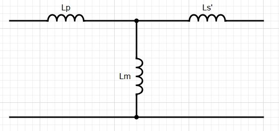
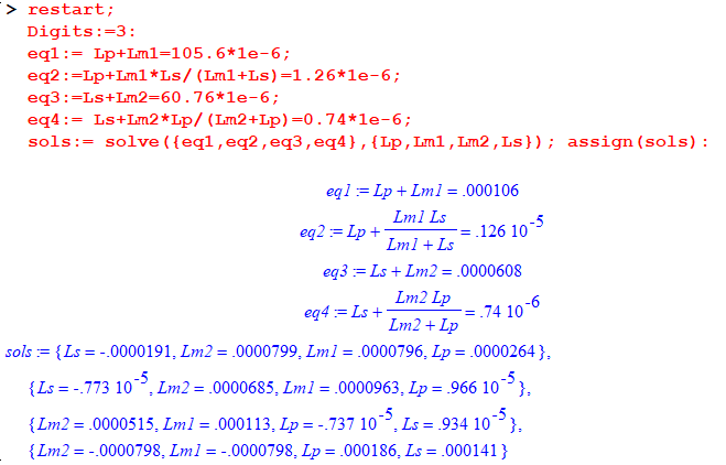
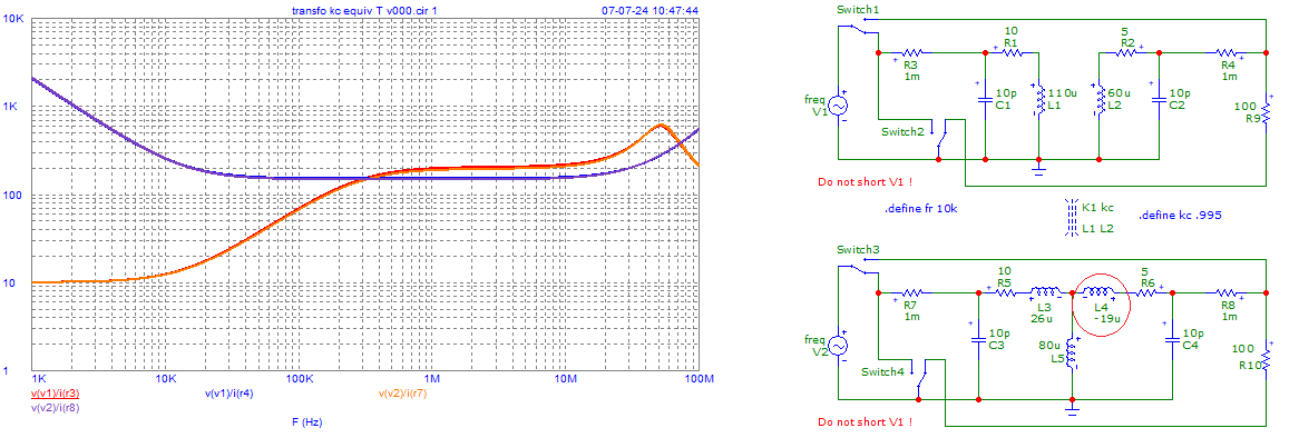
Are these values correct?
Yes and no. The values are correct for a particular model of a transformer, but the labels or meanings you have assigned to the components in that model are incorrect.
The transformer you describe consists of two coupled inductors that have self inductances of 105.6 uH and 60.76 uH. The self inductance of each coil is what you measure when you measure the inductance of that coil with the other coil open-circuit.

simulate this circuit – Schematic created using CircuitLab
We don't know the value of \$k\$ yet, but we will find it soon.
This model of coupled inductors is equivalent to a "T" model of inductors.

simulate this circuit
In this model M is the Mutual Inductance. It is NOT the what is called the magnetizing inductance. Further, the inductors I have labeled L1-M and L2-M are NOT "leakage inductances. In your model, you have Lp and Ls' which you describe as "leakage inductances". Your numbers are right, but those numbers do not refer to what is called "leakage inductance", but to inductances within this T model.
We can calculate the value of M using the measurements you took for the inductance seen on the primary with the secondary shorted, and for the inductance seen on the secondary with the primary shorted.
The inductance seen on the primary, with the secondary shorted is
\$(L_1 - M) + ( M \;||\; (L_2 - M)\;) = L_1 - \frac{M^2}{L_2}\$
Plugging in your measured values, we get \$M = \$ 79.6222 uH.
Similarly, the inductance seen on the secondary, with the primary shorted is
\$(L_2 - M) + (M\;||\;(L_1 - M)\;) = L_2 - \frac{M^2}{L_1}\$
which, using your measured values, gives \$M = \$ 79.61222 uH.
The calculations are close, but not exact. We will choose 79.617 uH as the value of M.
This makes our model

simulate this circuit
These numbers match your calculations, and this is a perfectly good model of your transformer. It just doesn't match your language regarding "leakage inductance".
Regarding the negative value of one of the inductances, this is typical of this model. It yields negative inductances. There is no need to be troubled by this negative value. It works fine in all the formulae you are likely to come across. Just remember that it is a negative value inductance, and enter it as such, and remember that it is not a leakage inductance.
Having found M, we can now find k in the original coupled inductor model.
$$k = \frac{M}{\sqrt{L_1L_2}} = 0.994$$
This is a very good coupling ratio, by the way.
Next we turn to leakage inductance.
Notice that in our derivation of the T model, we did not use the turns ratio. We only needed three parameters, L1, L2 and M. There are common (lossless) transformer models that require 4 parameters, and one of those parameters is, in a way, redundant. With the three parameters L1, L2, and M, we don't need to know the turns ratio. However, it turns out that we can't calculate leakage inductance in one of those models without assigning a turns ratio.
So, is there a problem? Actually, yes. You describe the turns ratio as 8:6, and physically, that may be true. However, if we calculate
$$\alpha = \sqrt\frac{L_1}{L_2}$$
we get \$\alpha = 1.318\$ which is near 8/6 = 1.333, but is different enough for us question the propriety of using 8/6 in our model. You can use either number, or even some completely made up number in the model, and this will affect how much leakage occurs on either side of the ideal transformer in our model, and will also affect any concept of the "total" leakage current. But all of the models will have the same circuit behavior. However, if we deviate too far from \$\alpha\$, one of the leakage inductances that is derived will become negative. That will be the case if we choose 1.333 as the value of n. So, we will continue the example using 1.318 instead of 1.333.
The model we will use is the following. There are many equivalent models, and I will not explain here how to transform from one to another.

simulate this circuit
In this model, the transformer is ideal, L_m is called the magnetizing inductance, L_k1 is the primary side leakage inductance, and L_k2 is the secondary side leakage inductance. "n" is the "turns ratio", which we will choose to have a value of 1.318, but which we could have chosen to be 1.333 or some other value.
The formulae we use to convert our previous model to the current model are these.
$$L_m = nM$$
$$L_{k1} = L_1-nM$$
$$L_{k2} = L_2-\frac{M}{n}$$
using the values found previously, we get
\$L_m =104.935\$ uH.
\$L_{k1} = 0.7\$ uH.
\$L_{k2} = 0.35\$ uH.

simulate this circuit
Now, just to do a quick sanity check to see that my numbers could possibly be accurate, will do a simulation of the two models.
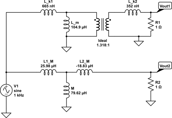
simulate this circuit
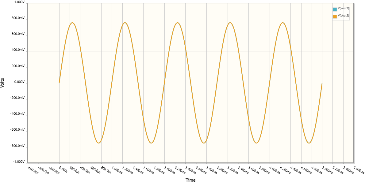
At least in this case, the two outputs match exactly, so I'm somewhat confident I didn't make any mistakes in my calculations.
