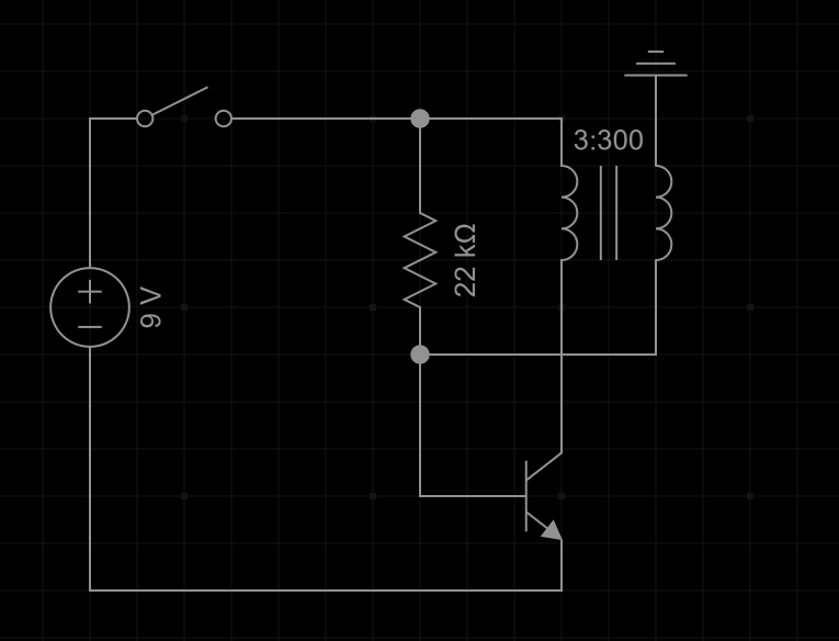
I have been looking at different designs for a simple slayer exciter circuit and have attempted to create a circuit diagram for it based on what I have seen from some other designs online. I just wanted to ensure that I have constructed the circuit correctly, specifically I have seen some versions with a diode/led and wanted to find out whether it could be removed and have the circuit still be functional.
-
\$\begingroup\$ You would probably do better to copy an existing (known functional) circuit rather than trying to design your own. This one from ElectroBoom looks good. It has a good description, a parts list, schematic diagram, and a video. \$\endgroup\$– JRECommented Jul 19 at 9:07
-
\$\begingroup\$ You could ground the secondary, this would make operating the switch "interesting" \$\endgroup\$– Jasen Слава УкраїніCommented Jul 19 at 11:19
4 Answers
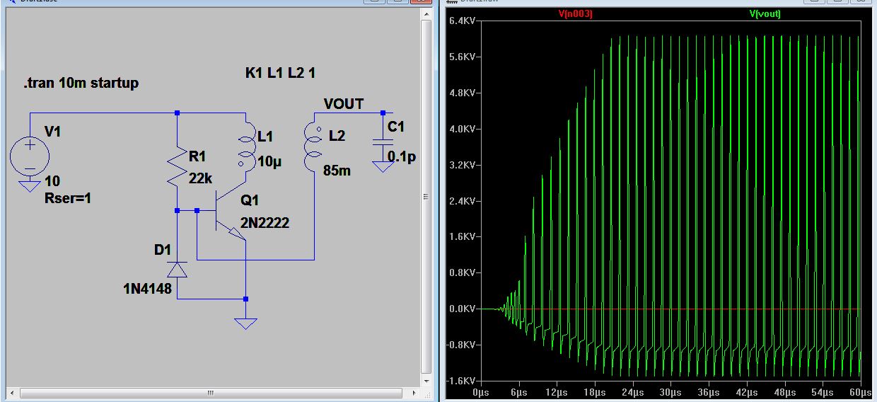
made with microcap v12
If you make your coupling very "low", you can get something like this.
Something like 24 kV peak to peak.
You can find the slayer exciter circuit from electroboom's website. Here is the circuit taken from there.
-
\$\begingroup\$ D1 is very important: it provides a current path for the output winding no matter what the polarity relative to ground is. The forward path is provided by Q1's VBE diode. \$\endgroup\$ Commented Aug 5 at 16:06
It seems you are 95% towards the "reinvention" of a circuit known as "Joule Thief". You can see it in action here. Note that the capacitors in the simulation, can be, but usually are not present in the real circuit, since the transistor and transformer already have enough capacitance to get stuff going. I suggest you work with already known topologies, and try simulating your ideas in things like the site above (or ltspice).
I don't know much about Tesla coils or "slayer circuits" but the joule thief can make pretty high voltages from surprisingly little. This creator shows how to build one: https://www.youtube.com/watch?v=K53beWYdIpc
Thank you all for the advice, I think I managed to figure out how to adapt it to make it work the way I intended it to. I have a video going through the build and explaining what I did for anyone else that may be interested https://youtu.be/7LdSCTs4pB8
-
2\$\begingroup\$ This is a link-only answer. You're welcome to answer your own question, but make it work even if YouTube were to disappear tomorrow. Link-only answers become useless after some time. Say 5 years from now you decide to get rid of your old YouTube videos - as many YouTubers do when they gain popularity. Or Google may suspend your account indefinitely on a whim (happens all the time). Then, suddenly, this answer will not be usable. Please edit this answer to describe what you did using text, schematics and pictures. The YouTube link will be just a bonus. \$\endgroup\$ Commented Aug 5 at 16:09


