2
\$\begingroup\$

Relay in use: https://www.mouser.com/ProductDetail/Omron-Electronics/G5LE-1-DC3?qs=Mrnyg3lK62ERI7jHW9tK%2Fg%3D%3D

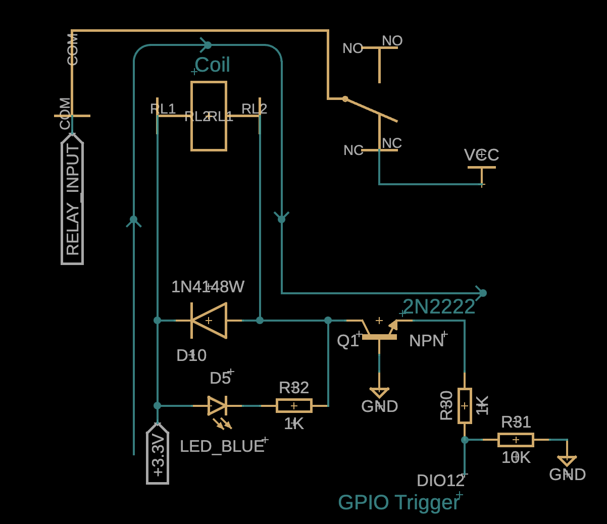
Vin = 12V Imax = ~5A

My application for the relay is to cut off downstream power with a µController, hence the 3V coil. A NC relay was chosen because I didn't want to energized the coil continuously, only when the downstream needed power cycled. We discovered that most relays like the one linked has a low shock rating and malfunctions pretty easily. Currently, due to large vibrations in a manufacturing environment, the relay is prematurely opening up causing the downstream to power off completely and it stays stuck open. I'm searching for any insight into the use of relays in an environment that has a lot of vibration. Is this the wrong application and should I be using an electronic load switch instead? I'm hesitant of using something solid state because of the continuous current that will degrade the component over time.

enter image description here

\$\endgroup\$
10
  • \$\begingroup\$ Continuous current doesn't degrade semiconductors; exceeding ratings does (even if momentarily, so all time scales must be considered). Is there any option to include power interruption (for defined period of time) in the load spec? \$\endgroup\$ Commented Jul 22 at 1:39
  • 1
    \$\begingroup\$ A few suggestions: 1. Shock-mount the relay, e.g., suspend it from 6 springs; top, bottom, and all sides. 2. Use a mechanical latching relay, which uses power only when energized, and opens and closes on alternate pulses. However, these often require more current then a 2N222 can pass. 3. As you suggest, replace the relay with a solid-state device. Handling 12 VDC at 5 A, 60 W with a low-impedance device, e.g., low-resistance MOSFET should dissipate less than a watt. Take care to bypass voltage spikes on switching, if an inductive load. \$\endgroup\$ Commented Jul 22 at 2:01
  • \$\begingroup\$ What are the logic voltages for DIO12? +3.3V or GND? If so, how does Q1 switch? Presuming that is a drawing error(Q1B at +3.3V could make sense). No reason to go with a relay - use a PMOS pass device with an NMOS/NPN inverter driven from DIO12, collector/drain to VIN=12V. Should be cheaper, smaller and not vibration sensitive. \$\endgroup\$
    – JkingNH
    Commented Jul 22 at 2:07
  • \$\begingroup\$ @JkingNH It is 3.3V logic, and apologies it is a library error. I appreciate your suggestion, If you could provide a schematic it would help me make more sense of what you are saying. \$\endgroup\$ Commented Jul 22 at 12:55
  • \$\begingroup\$ @TimWilliams Im lost on what you mean by power interruption in the load spec. Excuse my ignorance! \$\endgroup\$ Commented Jul 22 at 13:06

3 Answers 3

1
\$\begingroup\$

There do exist relays rated for high shock and vibration. They are a lot more expensive, but they do exist. Depending on the country you live in, you might have some difficulty getting your hands on one, though.

You can shock mount your relay as suggested in a comment to the question by Tim Williams. In industrial environments, the vibrations are actually relatively well defined. You don't often have too many different frequencies. If you can characterise the environment, you can design your mounting method to specifically dampen any peaks in the vibration profile. This could sometimes be as easy as carving out certain portions of the mounting plate to change the resonant frequency. Generally, you'd try to push the resonant frequency of your whole assembly atleast to about twice the frequency of any expected vibration, and avoid harmonics of any particular peaks you expect. Note that while relays fail easily in vibration, they aren't the only electronics that do. IC pins, solder joints, even FR4 laminates themselves could also flex and crack and snap if you find yourself resonating to the machine you're stuck to.

Simulating the 3d model of your design to extract the resonant frequency is a good way to start and should be enough for most applications. If you can, it's better to characterize your assembly on a shaker. Meshing the 3d models and getting all the components and couplings correct can be a little tricky for electronics, with lots of small masses with not very well specified joints. For industrial applications, I suspect either method will work just fine, so use whichever is easier / cheaper/ more accessible to you

That said, solid state relays are probably what you want. Mechanical degradation of mechanical relays happens a lot faster than degradation of solid state switches operating within spec. Size them well. If you're concerned about degradation, derate them. Usually, 50% is probably fine as long as you're confident you have no thermal issues. If it feels like they're getting hot, add adequate heat sinks and make sure you have a way of evacuating the heat - IPxx ratings can often be counterproductive to thermal management. Make sure you have a solution which maintains a stable temperature well below the max allowed temperature in continuous usage at max load in the worst possible ambient conditions.

\$\endgroup\$
2
  • 1
    \$\begingroup\$ I want to emphasize the part about "characterizing the environment". If you don't know what your shock and vibe requirements are (the environment), then you're just shooting in the dark. That's not engineering; it's hacking. \$\endgroup\$
    – SteveSh
    Commented Jul 22 at 14:49
  • \$\begingroup\$ It was DrMoishe :) \$\endgroup\$ Commented Jul 22 at 20:19
0
\$\begingroup\$

You could characterize the shock and vibration and choose a relay accordingly. Even from Omron, I wouldn't expect much from a $1.66 part to begin with so there's definitely room for improvement there. Or you could use a NO solid state relay that only needs a few mW to stay closed or a NC SSR for a bit more money.

\$\endgroup\$
0
\$\begingroup\$

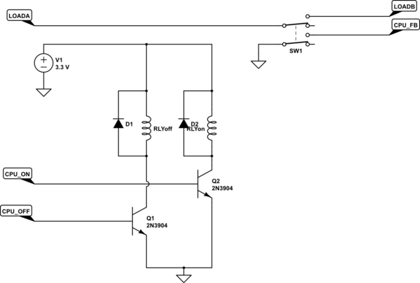
Consider a latching relay

  • Only uses power when changes state
  • Perhaps with a monitoring line to ensure correct operation
  • Albeit with extra code complexity

If your application will permit it, you could energise one of the two relay coils whenever the current state (according to feedback pin) isn't the currently desired state. In most microcontrollers you could use a pin-change interrupt so you're not polling.

schematic

simulate this circuit – Schematic created using CircuitLab

(Circuit assumes internal pull-up on CPU_FB.)

\$\endgroup\$
2
  • \$\begingroup\$ I actually tried a latching relay for a different application but experienced the same issues, allowing the lid to the enclosure to fall shut was changing the state and keeping the device on and subsequently draining the battery! I used a TXS2-3V and controlled it with a TMC7300-LA-T in half-bridge mode. \$\endgroup\$ Commented Jul 22 at 13:04
  • \$\begingroup\$ My suggestion is that your software would detect this (on CPU_FB) and reenergise the appropriate coil. It's essentially a system to monitor the failure and correct it. Whether your load would permit this depends on what kind of load you have. \$\endgroup\$
    – jonathanjo
    Commented Jul 22 at 13:07

Your Answer

By clicking “Post Your Answer”, you agree to our terms of service and acknowledge you have read our privacy policy.

Not the answer you're looking for? Browse other questions tagged or ask your own question.