1
\$\begingroup\$

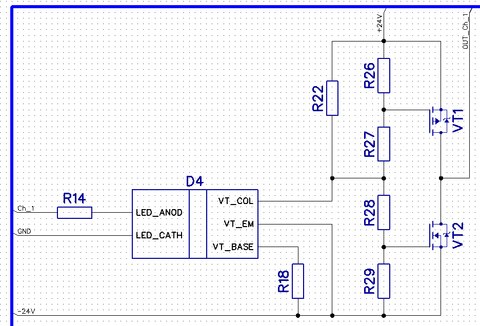
I want to protect the output channels of my device from overcurrent and short circuits, but I want the protection circuit to be less expensive than the device itself. An example of the output channel circuit is shown in the diagram, and there are 16 such channels in total. Could you please advise on how to do this correctly? Are there any well-known solutions that I might have missed during my search?

A fuse on the output channel won't work since it would need to be replaced, and I want to avoid that.

Ideally, this circuit should shut off the output channel after a short time, enough to prevent the output FETs from burning out. Then, I will figure out how to notify the MCU about the channel failure so that it doesn't turn it on again. Output channel example
\$\endgroup\$
4
  • \$\begingroup\$ Why not to measure the current with MCU and turn the channel off if an overcurrent occure? A speed issue? \$\endgroup\$ Commented Jul 30 at 10:30
  • \$\begingroup\$ @MichalPodmanický Because I only have 2 free pins left \$\endgroup\$
    – RUMBUFDSI
    Commented Jul 30 at 11:08
  • \$\begingroup\$ How much current are we talking about? Are we allowed to modify the circuit you showed us? \$\endgroup\$ Commented Jul 30 at 11:37
  • \$\begingroup\$ @SimonFitch The maximum current is about 3A. Of course, the circuit can be modified. There are no restrictions. \$\endgroup\$
    – RUMBUFDSI
    Commented Jul 31 at 6:38

2 Answers 2

0
\$\begingroup\$

How about using a poly-fuse that restores itself after some time? No replacement needed.

\$\endgroup\$
1
  • \$\begingroup\$ The semiconductor is dead long before such a fuse trips, except there is a huge overcurrent margin in the design. \$\endgroup\$
    – Jens
    Commented Jul 30 at 20:44
0
\$\begingroup\$

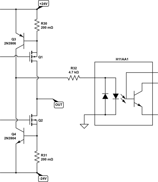
Below I am sensing source current in each output MOSFET with a resistor, and using the voltage they develop (in the case of over-current) to switch on either Q3 or Q4:

schematic

simulate this circuit – Schematic created using CircuitLab

If either Q3 or Q4 is switched on, then current flows via R32 to illuminate one of the opto-iosolator's LEDs. The opto-isolator will need to be an "AC input" type, such as the H11AA1. You can then use that opto-isolator's output transistor to signal the over-current condition to your MCU. LED current flows when source current in either Q1 or Q2 exceeds \$I_{ALERT}\$:

$$ I_{ALERT} \approx \frac{0.7V}{R_{30\&31}} = \frac{0.7V}{0.2\Omega} = 3.5A $$

With a further small modification, this same system could be adapted to implement current limiting, instead of just alerting, but your existing resistor arrangement at the MOSFET gates doesn't permit this.

There's also another big problem to address before you consider anything else. You will suffer a shoot-through condition, with many, many amperes of current flowing directly down through both MOSFETs, each time your control input signal changes from high and low or back. That's a completely different problem to solve.

You currently have no way to switch both MOSFETs off, which you will have to implement if you want your MCU to respond successfully to over-current. That will require further modifications to your design, in addition to the one I described above.

\$\endgroup\$

Your Answer

By clicking “Post Your Answer”, you agree to our terms of service and acknowledge you have read our privacy policy.

Not the answer you're looking for? Browse other questions tagged or ask your own question.