0
\$\begingroup\$

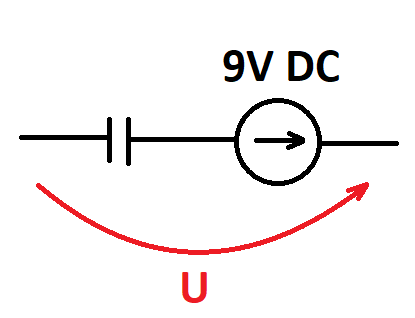
I am studying for my circuit theory exam and I came across a problem which is shown in the picture. What will be the voltage here?

I simulated a similar situation by connecting the negative terminal of a 9V battery to the negative terminal of an electrolytic capacitor, I measured the voltage with a multimeter between the positive terminal of the battery and the unconnected plate of the capacitor, which showed 9V which slowly decreased to 0. Where did the 9V voltage come from? How did the potential transfer from the capacitor plate connected to the negative terminal of the battery to the plate measured by the multimeter? Maybe I am wrong and this is a different mechanism?

My guess is that the negative terminal of the battery sends electrons to the capacitor plate which is charged negatively, and repels electrons in the opposite plate through the high resistance of the multimeter to the positive terminal of the battery. Is this enough to get 9V on the multimeter?

But looking at the theoretical situation, where there is no multimeter and there is a complete gap between the unconnected capacitor plate and the positive terminal of the battery, these electrons cannot move to the positive terminal of the battery. So what will be the voltage between the "hanging in the air" capacitor plate and the positive terminal of the battery? It reminds me a bit of a situation where I would measure the voltage between two separate circuits, then if I am not mistaken the voltmeter would read 0V because they are not connected anywhere. I am very confused about this

image

alternative link to image: https://ibb.co/px7DFpC

\$\endgroup\$

3 Answers 3

1
\$\begingroup\$

If there is nothing connected there is no circuit and this is not a circuits problem.

It becomes an answerable circuits problem when you specify what is connected (high resistance? short? another capacitor??). AND the initial voltage on the capacitor.

\$\endgroup\$
1
  • \$\begingroup\$ there is a circuit and a current loop. Vbat +DMM Zin and an e-cap with leakage current. \$\endgroup\$
    – D.A.S.
    Commented Aug 10 at 22:16
0
\$\begingroup\$

The voltage of your circuit is 9V, assuming the capacitor is discharged and there is no voltage over it. As there is no current flowing in an open circuit, capacitor voltage stays at 0V and the supply has 9V.

In a real world circuit, your multimeter has impedance, so it closes the circuit and current flows until capacitor charges to 9V. When capacitor is charged, there is no current flowing through multimeter so the voltage over multimeter impedance is 0V.

\$\endgroup\$
2
  • \$\begingroup\$ So when i'm doing circuit theory tasks, and situation similar to this from the image will appear, i always assume that voltage between two capacitor plates is 0V - when one plate is on 9V, second one will be on the same 9V? Does it come from first Kirchhoff law - no current, no voltage drop - 0V between capacitor plates, and second kirchhoff law: U = 9V + 0V = 9V? And do I understand correctly, I'm doing this calculation in state before capacitor charging process? \$\endgroup\$ Commented Aug 12 at 16:55
  • \$\begingroup\$ @MichałŁyczek No not really. The initial state of charge in capacitor may be anything. So it's also possible nothing happens in a circuit if you connect a 9V battery to a capacitor that is already charged to 9V too. If you are given a task to calvulate something, you should be given the startup state of the circuit as well. If it is not given then you could assume something but who knows if the assumption is correct. \$\endgroup\$
    – Justme
    Commented Aug 12 at 18:05
0
\$\begingroup\$

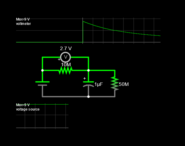
With the correct polarity, it will look like this depending on the leakage current rating R = Vmax/Imax

With the wrong polarity, the shunt resistance will be much smaller current limited by the DMM 10 Megohm input R.(typ)

my falstad image here

\$\endgroup\$
4
  • \$\begingroup\$ But what is the purpose of 50M resistance? \$\endgroup\$ Commented Aug 10 at 20:35
  • \$\begingroup\$ to emulate e-cap leakage. Did your expectation go to 0V? \$\endgroup\$
    – D.A.S.
    Commented Aug 10 at 22:14
  • \$\begingroup\$ I haven't heard about it yet, voltage was decreasing but i didn't wait until it reach exactly 0V, but my question is mainly about why 9V is measured at the beggining on multimeter, immediately after connecting it, and will the voltage U in the drawing also be 9V similarly to real connection? \$\endgroup\$ Commented Aug 11 at 0:03
  • \$\begingroup\$ THat depends if the cap has memory of a stored charge, but if it starts at 0V then the meter measures the difference. \$\endgroup\$
    – D.A.S.
    Commented Aug 11 at 3:37

Your Answer

By clicking “Post Your Answer”, you agree to our terms of service and acknowledge you have read our privacy policy.

Not the answer you're looking for? Browse other questions tagged or ask your own question.