0
\$\begingroup\$

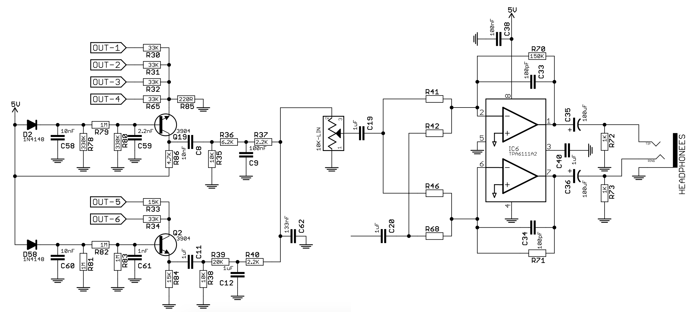
I'd like to modify this circuit (output stage of a digital audio synthesizer) because the signal going into the headphones amp (TPA6111A2) is too low, probably because of the passive filtering before the potentiometer.

With such low signal, I'd need a really large gain (about x150) to get a good audible signal on the output, but using that much gain I'm getting excessive noise and distortion on the output (the TPA6111 datasheet suggests a gain range of 0 to 20).

The signal balance between the two paths joining at thee potentiometer wiper, and the frequency response, is spot on with what I want, but I'm wondering if there is a way to modify the filters to reduce their passband attenuation without altering balance and frequency response, so that I can use a lower gain on the final stage?

The signals labelled as OUT-x are digital square waves (3.3V) outputs from a microcontroller. I guess the two transistors Q2 and Q19 are providing some form of distortion/waveshaping (that I'd like to keep). The amplifier is also mixing another signal via C20 (still to be defined).

Also, I assume all the circuitry on the bases of the two transistors could probably be simplified (it came up like this from experimenting)

schematic

(The schematic was drawn by me after experimenting on breadboard.)

\$\endgroup\$
6
  • \$\begingroup\$ The significant attenuation comes from your common base input R ratios. Actually none of it looks linear. \$\endgroup\$
    – D.A.S.
    Commented Aug 22 at 15:08
  • 1
    \$\begingroup\$ OUT-1 thru OUT-4 are attenuated by a factor of about 150 by R85. OUT-5 and OUT-6 are digitally OR'd together -- not sure what the intent is there. \$\endgroup\$
    – Dave Tweed
    Commented Aug 22 at 15:17
  • \$\begingroup\$ Dave agrees. Also The diode is on the wrong side to compensate Vbe and the supply PSRR is poor. and Q2 is not a CB mixer. \$\endgroup\$
    – D.A.S.
    Commented Aug 22 at 15:28
  • \$\begingroup\$ I suggest you define goals (specs) gain, I/O impedance, BW, THD, PSRR then define problem. \$\endgroup\$
    – D.A.S.
    Commented Aug 22 at 15:49
  • \$\begingroup\$ I admire your tenacity to make a uC based Class ? amplifier low distortion, but some theory is impeding your progress. \$\endgroup\$
    – D.A.S.
    Commented Aug 22 at 16:08

1 Answer 1

0
\$\begingroup\$

Well you could look at R36 and R39. Both these form a low pass filter on their respective channels, but the use of a series resistor will attenuate the signal.

R36 and C9 form a low pass filter with a cutoff frequency at 2586Hz. You can work this out with $$ F = \frac{1}{2*pi*R*C} $$ You'll see R and C are on the same side of the fraction, so you can preserve the cutoff frequency by doing the opposite to both. So you can halve the resistor to decrease the attenuation and double the capacitor to preserve the cut-off.

You can do the same for R39 and C12. To be clear, I've not simulated this circuit and cannot be sure changing these values won't have another undesired effect, but play around and see if you get the results you looking for.

\$\endgroup\$

Your Answer

By clicking “Post Your Answer”, you agree to our terms of service and acknowledge you have read our privacy policy.

Not the answer you're looking for? Browse other questions tagged or ask your own question.