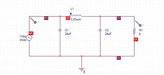
Hi I built a simple LC low pass filter and I supply it with a 1 V peak to peak AC voltage at 200 Hz from a function generator. My cutoff is set at 700 Hz and I have selected my circuit components based on this cutoff. However, when I hook up my circuit to the oscilloscope both the input and output seem to be attenuated when measured on the oscilloscope. The input and output shows up to be around 150 mV peak to peak instead of 1 V peak to peak. I believe the capacitors have something to do with this attenuation. What are your suggestions to solve this problem?
-
\$\begingroup\$ Do you find this result in your simulation or with a bread board circuit in a lab? Sometimes the probe on the oscilloscope is set to 10x or 100x and can give you results you did not expect. Also, the function generators at my school do not output exactly what it says it does (usually double or half the value indicated) so make sure that with no load your signal is 1Vpp. \$\endgroup\$– Josh JobinCommented Oct 14, 2015 at 15:14
-
\$\begingroup\$ I did the measurements in lab on a breadboard circuit. The scope probes are fine and it is not a problem of 10x or 100x. The function generator works fine without the load. I will upload a screen plot of the attenuation soon. \$\endgroup\$– TimmyCommented Oct 14, 2015 at 15:18
-
2\$\begingroup\$ Are you really using an 8 Ohm resistor as a load? if so that is probably causing the attenuation - you need a fairly meaty signal source to supply that, without it being affected. \$\endgroup\$– IcyCommented Oct 14, 2015 at 15:29
-
\$\begingroup\$ It looks like your function generator gets loaded too much. Speaking of function generators (at this frequency): youtu.be/06btgjAV3Hk?t=136 I haven't done calculations, but it looks like what you have there would need a power amp to drive. Also, this is not a "simple LC low pass" but a pi filter. \$\endgroup\$– got trolled too much this weekCommented Oct 14, 2015 at 15:30
-
\$\begingroup\$ Yes I need to drive a 8-Ohm Resistor as a load. The function generator does have 50-ohm output impedance. Yes it is a pi filter as well. \$\endgroup\$– TimmyCommented Oct 14, 2015 at 16:55
1 Answer
If your function generator has a 50-ohm output impedance, I think your results make sense.
$$Z_{C1} = Z_{C2} = \frac 1 {j 2 \pi \cdot 200\ \mathrm{Hz} \cdot 28\ \mathrm{\mu F}} = -j15.9\ \mathrm \Omega$$
$$Z_{L1} = j 2 \pi \cdot 200\ \mathrm{Hz} \cdot 3.63\ \mathrm{mH} = j4.6\ \mathrm{\Omega}$$
Using series and parallel combinations, I get a total impedance of \$6.4 -j1.3\ \Omega\$, or \$~6.6 \angle -11 ^\circ\ \Omega\$ in polar notation. With a 50-ohm output impedance, your expected scope voltage on the input would be:
$$1.414\ \mathrm V \frac {6.6\ \Omega} {50\ \Omega + 6.6 \Omega} \approx 165\ \mathrm{mV}$$
That's amplitude, not peak to peak, so maybe I'm missing a factor of two somewhere in my calculations, or maybe there's some other limit on the generator output. Regardless, that is the right order of magnitude to expect. You can't hook an ~8-ohm load up to a 50-ohm generator and expect to see the full generator voltage.
-
\$\begingroup\$ You might have omitted the effect of R1. The question is not really clear whether he's measuring the input with or without R1 in the circuit. \$\endgroup\$ Commented Oct 14, 2015 at 16:03
-
\$\begingroup\$ At 200Hz it doesn't make a whole lot of difference: imgur.com/a/tYZxo, but it looks like he measured with R1 in. \$\endgroup\$ Commented Oct 14, 2015 at 16:55

