I am trying to build a simple circuit to read from a pressure sensor using an Arduino Micro.
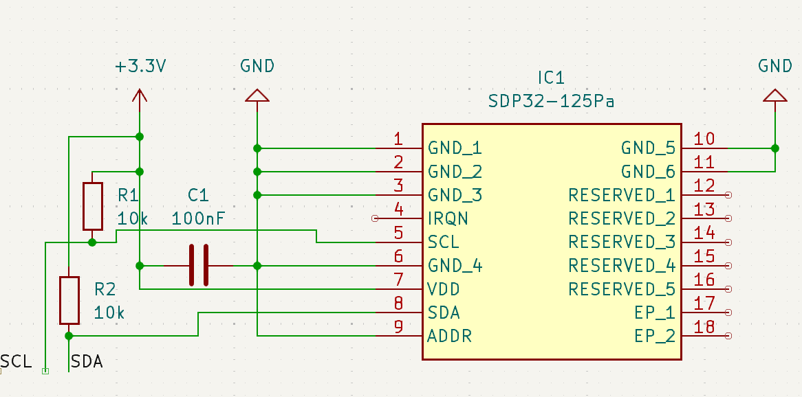
I looked at the datasheet and have a breadboard circuit which can be schematised as:
I know this isn't the best laid out schematic but I wanted to make sure every connection was explicitly drawn.
All grounds go to ground, reserved pins and IRQN are not connected, SDA and SCL go to the corresponding pins on the Arduino. R1 and R2 are meant to act as pull-up resistors. C1 is meant to be the decoupling capacitor.
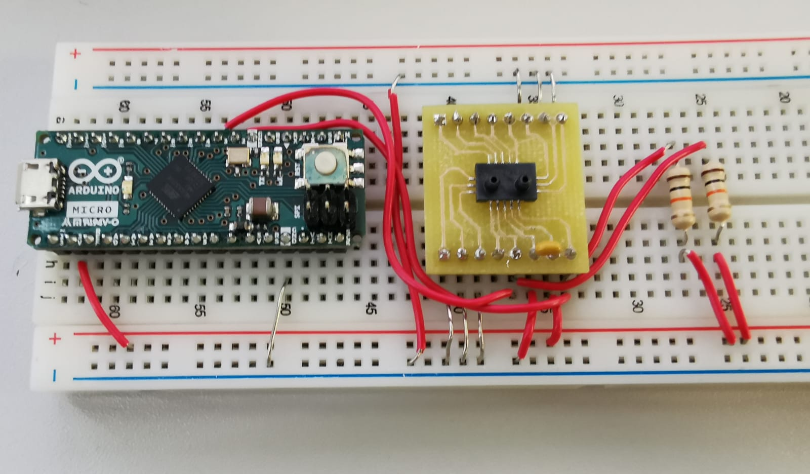
This is the real circuit on the breadboard:
Everything seems to connect where it I think it should and there aren't any obvious shorts.
If I run the Arduino I2C scanner I get:
--- Scan started ---
No I2C devices found
--- Scan finished ---

--- Scan started ---
Unknow error at address 0x52
Unknow error at address 0x7B
No I2C devices found
--- Scan finished ---

--- Scan started ---
No I2C devices found
--- Scan finished ---

...
There is no consistency in the error addresses and the scanner works separately with a different device. This implies that something about my circuit is wrong and, at least from the datasheet, I'm not sure what.
My best guess is that I've done the pull-up resistors or decoupling capacitor incorrectly (or there's some basic assumed background I don't have).
What am I missing here?
Misc. potentially useful info:
- I did not solder the pressure sensor to the breakout board but trust the person who did so I don't think there's a connection issue with the actual sensor.
- The true capacitance of the decoupling capacitor is closer to 110nF (measured using a multi-meter).
- The true resistance of the resistors is around 9.8 kohms.
If I can provide any other information which would be of use, please let me know.
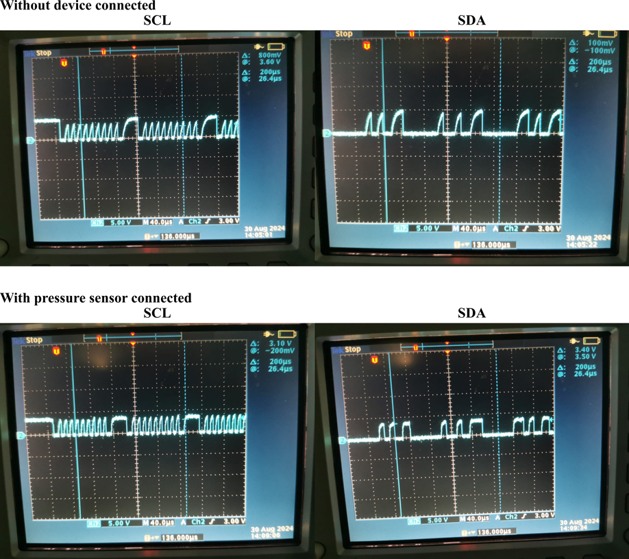
Edit - scope outputs:
Turns out we have quite an old scope with no way to get digital images out so here are some phone photos.
The clock timing seems different with the device attached. The voltage also doesn't seem to go fully high.


