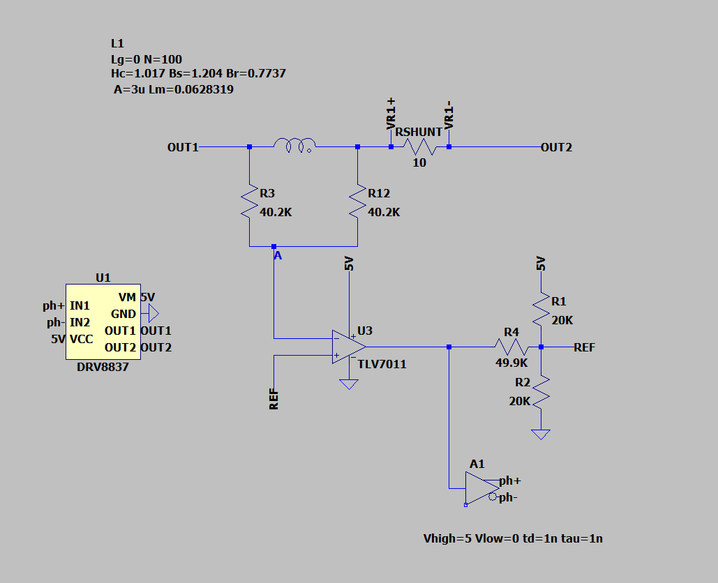
I am working on the following exitation circuit for a fluxgate sensor:

The exitation circuit's purpose is to drive the coil (inductor on schematic) deep into saturation in both positive and negative directions. It consists of:
Motor driver DRV8837, which is basically a H bridge that takes complementary PWM inputs.
Resistors R3 and R12, which forms a voltage divider and the voltage at point A is (5V / 2) + (I * RSHUNT). This voltage represents the current on the inductor and is input to the comparator.
A comparator TLV7011 forming a schmitt trigger together with R1, R2 and R4. Its purpose is to invert the direction of drive current when a certain threshold, set by R1, R2 and R4, is reached.
A1, inverter to generate phase- signal for the motor driver.
It is advantageous for the signal conditioning circuit(not shown on schematic) when the exitation frequency is higher. The exitation is considered noise, therefore it can be removed better if its frequency is higher. However, it looks like the only way to increase the frequency is to increase the power supply voltage, which is not possible in this design. I am thinking of using a capacitor to recycle the energy used in each half period of exitation, and use it in the next half. However, I am not able to get anything useful by using trial and error capacitor placement and value selection.
Any pointer on how the frequency could be increased or general pointers will be greatly appreciated!
Z
