0
\$\begingroup\$

I am using a 24MHz microchip oscillator to drive an Lattice FPGA clock input. The design failed radiated emission at 720MHz by 17dB which is even harmonics (24MHz x 30). When I used a near-field probe, I can see the strong peak at 720MHz right at the oscillator. My questions are:

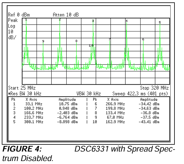
  1. What causes the even harmonics? From a Microchip AN, this seems oscillators (not the one I use) can generate even harmonics in general. enter image description here
  2. If I add a RC filter on the clock signal to attenuate this, what are the concerns?
  3. Any other solutions to attenuate this?
\$\endgroup\$
5
  • \$\begingroup\$ it would be helpful to see the radiated emissions plot -- so we may see if it is a narrow peak or maybe more broadband, as well as seeing other harmonics and how they play out. also, a schematic would help. \$\endgroup\$
    – rohmeooo
    Commented Sep 17 at 0:03
  • \$\begingroup\$ What is the duty cycle of the waveform? \$\endgroup\$
    – qrk
    Commented Sep 17 at 0:07
  • \$\begingroup\$ Your datasheet suggests that the LO output is not sinusoidal. Thus, even harmonics are expected even with a slight duty cycle error, which apparently this IC provides no correction for. \$\endgroup\$
    – a360pilot
    Commented Sep 17 at 0:59
  • \$\begingroup\$ Your odd harmonics are much higher in amplitude than the even ones. In the spectrum you show the 3rd harmonic is nearly 40 dB stronger than the 2nd harmonic. For a fully symmetric waveform the even harmonics should cancel out but any departure from symmetry will cause the even harmonics to become present. Ultimately the spectrum for a repeated impulse is a descending set of both odd and even harmonics with amplitude inversely proportional to harmonic number. \$\endgroup\$ Commented Sep 17 at 1:54
  • \$\begingroup\$ don't focus on filtering your clock signal. Fix the 720 MHz layout resonance. There should be a loop or stub of the correct size near your oscillator \$\endgroup\$
    – tobalt
    Commented Sep 17 at 4:09

5 Answers 5

2
\$\begingroup\$
  1. I'm not sure, but i believe even harmonics in an otherwise "square" wave are caused by the duty cycle not being exactly 50%. But don't quote me.
  2. You would be reducing the edge rate of your clock -- i.e., making it "more sinusoidal" and "less square". Some ICs don't like this and it can cause latchup or, more likely, jitter.
  3. I suggest you focus on your layout.
    Do you have ample bypass capacitance on the input of your oscillator? A ferrite bead on the input can further help prevent this noise from coupling back into the power input (e.g., the 1.8V/3.3V rail that runs it). Regarding the clock output -- minimize the length of this trace, make sure it is screened by GND wherever possible (embedded within GND planes, ideally), and of course, make sure it is routed with appropriate transmission line impedance. Finally, contradictory to my saying "minimize the length", there can be such thing as too-short -- if the wiring is very short and the pin it drives has low capacitance you may get some very sharp edges. Think of it as the output impedance of the clock as an RC filter into the parasitic capacitance. However, I doubt 30x even harmonic, alone, would appear because of that, so I'm thinking it is inadequate input bypassing (inadequate capacitance and/or layout) or bad transmission line characteristics of the clock trace.
\$\endgroup\$
1
  • \$\begingroup\$ The edges not being perfectly sharp (i.e. a trapezoidal wave instead of a square wave) also produces even harmonics, as I recall. \$\endgroup\$
    – Hearth
    Commented Sep 17 at 1:58
1
\$\begingroup\$

what creates even harmonics?

In general it is where the same thing happens twice per cycle.

in analoge we have zero-crossing and in digital we have fast edges...

If these events cause shoot-through between the power rails there's a current spike and depending on layout and decoupling the potential for that to be radiated.

\$\endgroup\$
1
\$\begingroup\$

It’s unlikely the duty cycle of the 24MHz signal itself is causing your 720MHz. If the 24MHz trace is in fact radiating 720MHz then it’s due to its edges being too fast. Make sure you’re using the slowest version of the chip, DSC1001 (the /3 and /4 versions will have much higher edge rates and you certainly don’t need that for 24MHz to an FPGA).

You can put a small resistor (20-75 ohm) in series, no capacitor necessary, to calm any over/undershoot without harming the 24MHz too much.

But it could be that it’s actually the FPGA that’s the source of the problem. Does it implement a PLL that’s generating a new, higher internal frequency?

FPGA compilers often default outputs to have unnecessarily strong drivers. Unless absolutely necessary, make sure all FPGA outputs are configured to use the wimpiest output drive (usually 4mA) and have the slew rate control set to SLOW. It’s rare outputs have to be any stronger than that.

\$\endgroup\$
1
  • \$\begingroup\$ Note that the 24MHz may be a system clock, and therefore most any output of the system (assumption: traditional synchronous design) will be synchronous to it. We cannot conclude from given information whether it is the clock itself, or any other signal in the system. It might well be the clock trace is short, simply going from oscillator to FPGA, and changing the oscillator signal has no effect at all. \$\endgroup\$ Commented Sep 17 at 4:28
1
\$\begingroup\$

While 30 is an even number, once the harmonic multiplication gets that high, it's best just to think of it as a 'high' harmonic. You only need to be a few percent away from 50% and your even 30s will not cancel.

As you say 720 MHz is a strong peak, it sounds like that's the only harmonic that's significant. You should suspect there is a resonance somewhere that's failing to suppress its emission.

Alter the decoupling on the oscillator and see if anything changes, remove or double the smallest capacitor closest to the IC. You might be seeing a decoupling resonance between the L of the leads of a large capacitor, and the C of a small one in parallel. While it doesn't happen very often, it's easily overlooked, and is a very quick and easy test to do.

And as td127 says, turn the speed down on anything that doesn't need it.

\$\endgroup\$
1
\$\begingroup\$

Even harmonics have to do with the balance (evenness, if you will!) of the waveform. An ideal 50% square wave is perfectly balanced (an odd function, the second half is inverse of the first half) so has none, only odd harmonics. A real signal is never quite this well balanced, and we can see this trend from the referenced spectrum.

The spectrum of a real square wave can be described in terms of these aspects, or modifications, and their direct consequences in the Fourier domain:

  • Starting with a square wave, we have odd harmonics (1, 3, 5, ...) going as 1/N amplitude, i.e. an overall -20dB/dec trend.
  • The trend continues until the risetime; the waveform is actually trapezoidal, and the slope of that trapezoid corresponds to the next breakpoint, beyond which it goes as 1/N^2.
  • Which goes until the corner rate; the waveform is actually a piecewise quadratic, and the curvature of the corners of the slopes correpsonds to the next breakpoint, beyond which it goes as 1/N^3.
  • And so on. Or perhaps the cutoff is more exponential in nature, and harmonics just kind of tank beyond some point. (There's never a hard cutoff in reality, a "brick wall filter" that would give rise to Gibbs phenomenon -- though we can construct filters precise enough to approach it, e.g. sinc interpolation in DSP filters.)

These trends correspond with aspects of pure waveforms, pieced together to make one franken-waveform. Consider the waveform series produced by integrating the square wave: you get a triangle, then a piecewise parabola, and so on; the harmonics go as 1/N, 1/N^2, ... . These correspond to the breakpoints above, where some smaller aspect of the waveform has been piecewise patched together with a scaled segment of the given waveform.

At this point, we have the trend of harmonics dropping off, but no even harmonics:

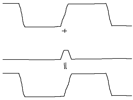
  • Consider the case for the timing being slightly off. Maybe it's 49.9% instead of 50%. The source might be an ideal 50% logic function (like a type-T flip-flop), but minor differences in propagation delay (rising vs. falling) create an imbalance. We can express this as the sum of an ideal 50% square wave, plus a tiny pulse of the time difference, aligned just such that it apparently distorts the duty cycle:
    enter image description here

    This short pulse has a flat spectrum until frequencies comparable to its duration, at which point harmonics go as 1/N, and then by risetime and curvature and so on. (Actually it's a sin(f T/D) thing and more complicated than that, but this hand-wave captures the general roll-off of it anyway.)

  • The rise and fall can be asymmetrical, in which case we have two pulses, one up, one down, of different rates. We have a spikier difference waveform, which may result in a different trend for the harmonics up to the break point.

  • CMOS logic outputs are inherently asymmetrical: PMOS performs about 2.5 times poorer than NMOS (that is, in terms of capacitance times RDS(on), or capacitance divided by gm), and we make up for that by using, usually double the area PMOS than NMOS, as a compromise between increasing node capacitance (makes both edges run slower) and reduced current capacity (drives a load e.g. trace + pin capacitance slower). Typical LVCMOS pin drivers are 30-50Ω RDS(on) pulling down, and 50-80Ω pulling up.

It's likely this is what the waveform in question is doing: the slope and curvature of the rising and falling edges aren't symmetrical, and the difference dictates even harmonics, in this case rising to a point, then falling together with odd harmonics as overall risetime takes over.

Out at 720MHz, you are likely to see a forest of peaks, spaced 24MHz apart, and more or less even in amplitude from one to the next; clusters of these may be selected by various filtering elements inherent to the system's EMC profile (shape and orientation of traces, PCB, connectors, etc.), resonances which can be broad (a rounded "forest canopy" of peaks) or very sharp (one harmonic happens to land within the passband and stands out above the rest).

But just as well, you don't mention if there are other sources in the system: a receiver input, a PLL, other oscillators, etc.; the 720MHz tone might not be related to the 24MHz at all.

As you do not give schematic, datasheets of relevant components, timing requirements (e.g. jitter), the particular offending spectrum, PCB layout, and arrangement of the physical system in test (e.g. photos), I cannot comment further on your EMC situation, in terms of what exactly is going on, nor what possible solutions might apply.

Understand that EMC problems are holistic in nature: potentially any aspect of the system (component value, type, trace dimensions, board outline, enclosure, connectors, cable orientation, etc.) may be relevant at some frequency or another. There is very little that can be assessed without the above data; and even so, diagnosis is lengthy and not well suited to this venue (a simple one-question one-answer format). If you are having persistent difficulty, and are unable to publicly discuss the project in such detail, I would suggest engaging a local EMC expert to assess your project.
\$\endgroup\$

Your Answer

By clicking “Post Your Answer”, you agree to our terms of service and acknowledge you have read our privacy policy.

Not the answer you're looking for? Browse other questions tagged or ask your own question.