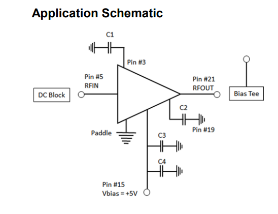
1)What is the purpose of the capacitors in the circuit?
The datasheet tells you that C1 and C2, suggested values of 1 uF, are needed for biassing at low frequencies. As the IC is specified down to 9 kHz, you can assume that some bias voltage dividers come out to those pins, and that signal-induced variation of the voltage will cause problems, perhaps distortion. As they say they are needed at low frequencies, it's possible that smaller values, or even none at all, might do at higher frequencies. You might do the experiment.
C3 and C4, suggested values 100 pF and 1 nF respectively, are the normal bias supply decoupling you might expect to find next to any IC.
2)How should I handle impedance matching?
The datasheet shows S11 and S22 as -15dB or better over most of the frequency range, and better than -10dB over the whole range. This means the IC is nominally matched, and you need do nothing more than aim for a nominal 50 ohms for the items you connect to it.
3)How does the DC biasing work, and what role does the bias tee play?
You need to supply some current to the output pin through an inductor. The datasheet is silent on how much current flows into the output, and how much into pin 15. Assume worst case that all the supply current must flow through the bias Tee inductor. The inductor must not load the output pin at RF.
This inductor is perhaps the most difficult component in the whole amplifier to get right. It's a bit disingenuous of the manufacturer to neglect to put in some hints to how you might provide it, especially given that they've included part numbers for the capacitors.
At its simplest, for a narrow range at high frequency, it need only be a λ/4 line. If you want to go down to 9 kHz, then you will use several inductors in series of different sizes, each damped with a shunt resistor, with perhaps a λ/4 line nearest to the line.
Several manufacturers do offer matched packaged bias inductors or complete bias Tees for particular frequency ranges, at a price, if you don't want to design your own.
The DC blocks, both on the input, and the one that completes the output bias Tee, can usually be purchased as single components for a price. Although they look like a simple capacitor, you can easily get suck-outs in the many GHz with standard capacitors if you are using a large value to get down to a low frequency. As with the inductor, it's easier with smaller bandwidths.
Your question, and the answers it attracts, would be much improved by specifying what range 'higher frequencies' means to you.

