0
\$\begingroup\$

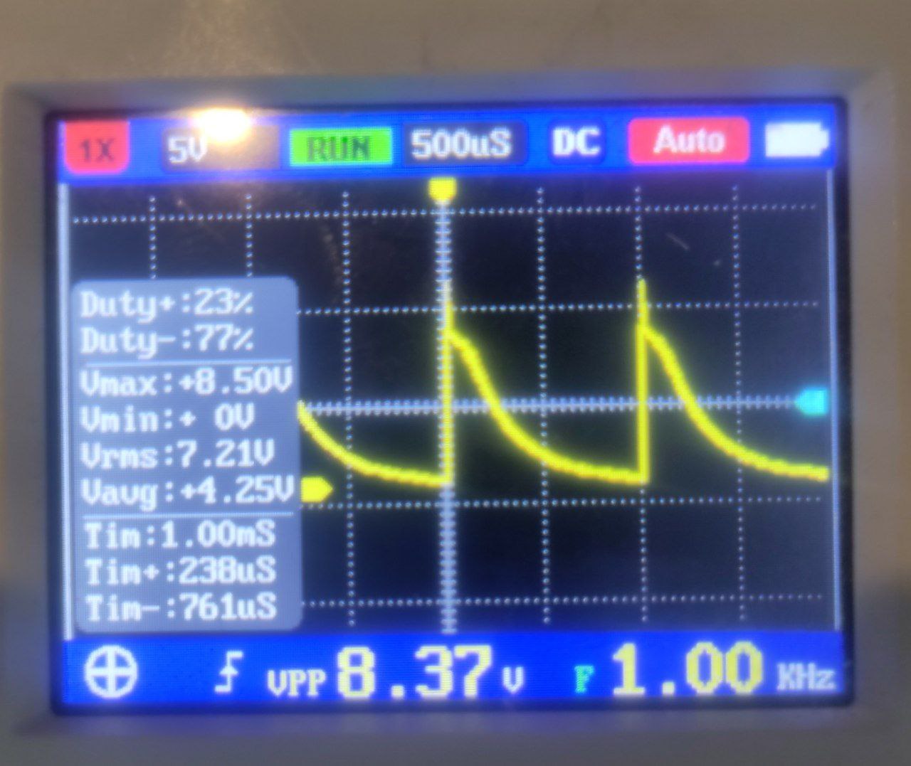
I want to drive an RGB-LED with 3 PT4115 ICs. But as soon as a single and short signal is applied to PWM_3.3V, the voltage wont drop in time, so LED starts to dim. You can see the Voltage of the LED in this picture:

OSC1

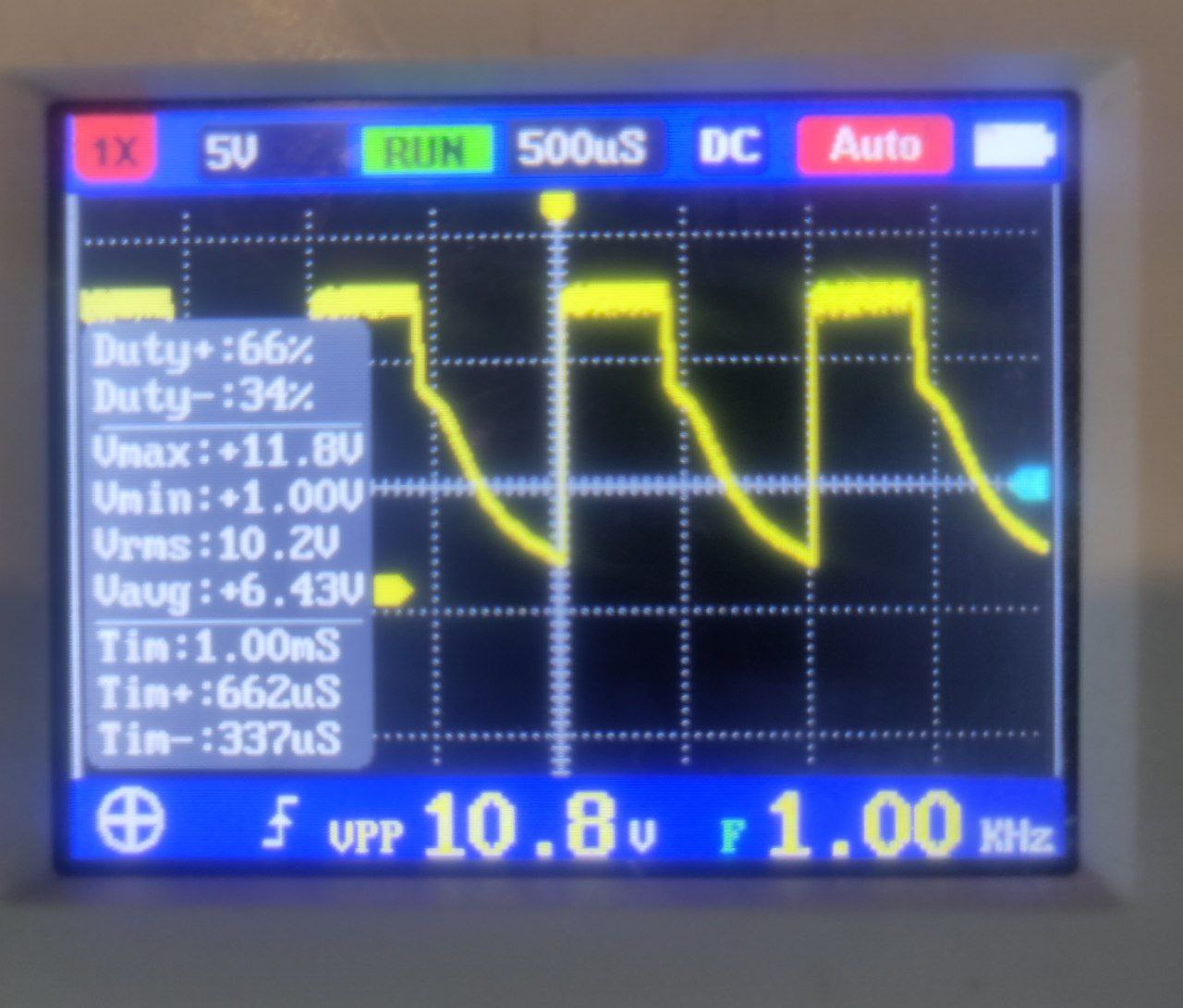
When duty is about half of the cycle:

OSC2

I already changed the inductor from 47uH to 22uH, and tried PWM frequencies from 500Hz to 2 Khz, but that didn't change anything. What could be the problem?

This is the schematic of a single channel: Schematic
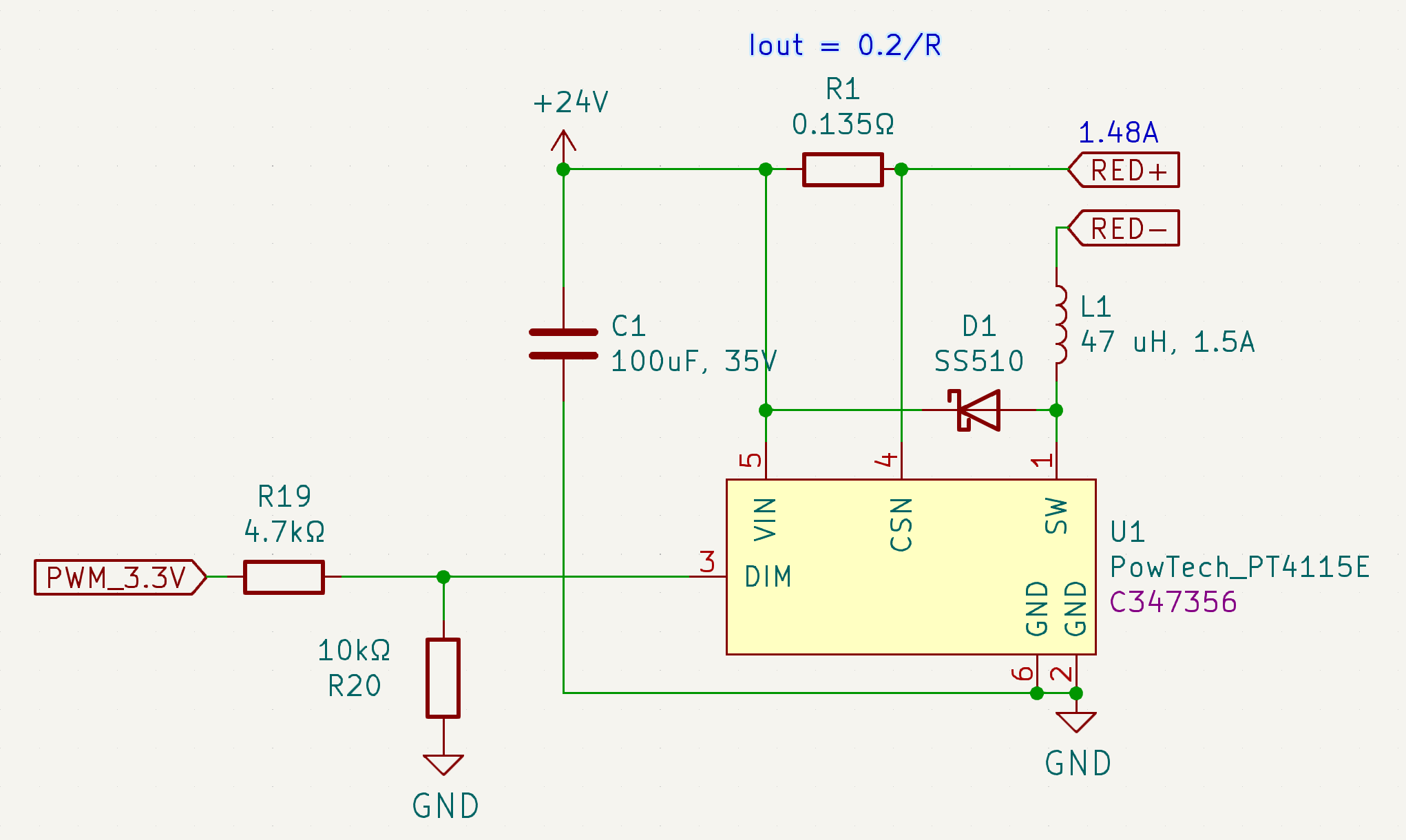
Thank you in advance :)

\$\endgroup\$

2 Answers 2

1
\$\begingroup\$

This is current controlled so you should be measuring LED current (or shunt voltage) not LED voltage, that would give you more meaningful measurements.

Also check with the oscilloscope the PWM signal directly at the DIM pin.

The PT4115 uses the DIM pin in 2 ways:

  • PWM with a logic high >2.5V and low <0.3V performs the duty cycle based dimming
  • DC voltage between 0.5V and 2.5V sets a constant current and there is an internal 200k resistor to 5V

You might be getting some combination of these two modes because of the voltage divider that you have (although with a quick calculation I don't think so).

\$\endgroup\$
0
\$\begingroup\$

Many thanks for the hint. You were right, the problem was a combination of wrong resistor values in the voltage divider and a too high pwm frequency. The Solution for me was

  • change R19 to 1kΩ
  • change R20 to 4.7kΩ
  • change PWM frequency to 200 Hz

The voltage drop of the pwm signal is now about 0.6V, so I get a clear high signal with level of about 2.7V. I also get nealy sharp edges with a lower PWM frequency.

\$\endgroup\$

Your Answer

By clicking “Post Your Answer”, you agree to our terms of service and acknowledge you have read our privacy policy.

Not the answer you're looking for? Browse other questions tagged or ask your own question.