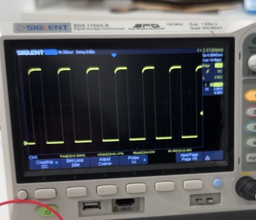
I'm using a 555 for PWM at 2.4 kHz to control a DIY brushless motor. The output of the 555 is going to the gate via a 1 kΩ resistor. At 240 Hz, the waveform has a flat top. At 2.4 kHz, it's rising slowly. I thought the 555 had enough current control the gate better at much higher frequencies than 2.4 kHz. I thought it could be too high of a resistance to the gate at 1 kΩ, but the waveform looks the same on both sides of the resistor. If the resistor was limiting the current too much, wouldn't the waveform be square before the resistor and rounded after? Do I really need a gate driver to get fast switching using a 555 and IRFZ44?
-
5\$\begingroup\$ The oscilloscope shot is meaningless without (a) it being in focus, (b) you describing what the waveform is and (c) showing that node on a schematic (not included). \$\endgroup\$– Andy akaCommented Nov 7 at 18:19
-
3\$\begingroup\$ Please post a scope shot with the timebase expanded so the rising edge slope fills half of the screen. \$\endgroup\$– AnalogKidCommented Nov 7 at 19:03
-
3\$\begingroup\$ You should specify exactly which MODEL of the 555 (Bipolar or CMOS, NE555, ICM7555 or TLC555) and you need to include a PICTURE of your setup, or at least a SCHEMATIC or its relevant portion. And what is your supply VOLTAGE, which is also important here. You need to include more details to get a proper answer. And a 1kΩ resistor value is definitely too high if your want to drive a MOSFET gate fast. Typical values are from a few ohms to a couple tens of ohms. \$\endgroup\$– Edin FifićCommented Nov 8 at 8:11
2 Answers
At 2.4KHz, it's rising slowly.
I see no problem. The top does not need to be flat. It's not the flatness of the top that matters. It is the slew rate of the rising and falling edge, measured in V/us. That's what you should be checking, since that's what drives losses.
To see what's going on you probably need to set the sweep rate between 1μs/div and 10μs/div. Much, much smaller timescale than what you're looking at as shown on the oscilloscope shot.
Do I really need a gate driver to get fast switching using a 555 and irfz44?
How do you know that your switching is not fast enough when you have not shown any waveforms that are on a timescale short enough to actually determine that?
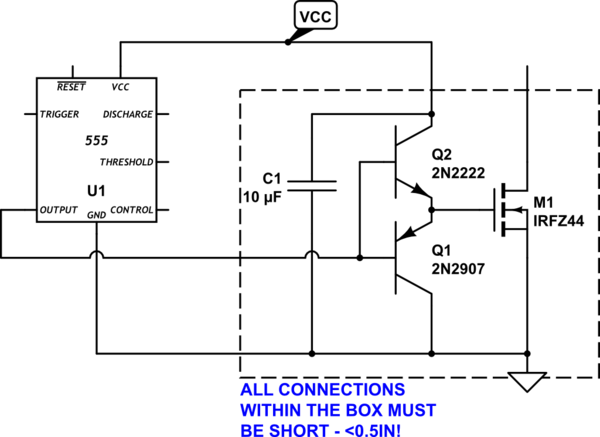
A "gate driver" can be as simple as a complementary emitter follower attached to the output of the 555.

simulate this circuit – Schematic created using CircuitLab
C1 should be ceramic.
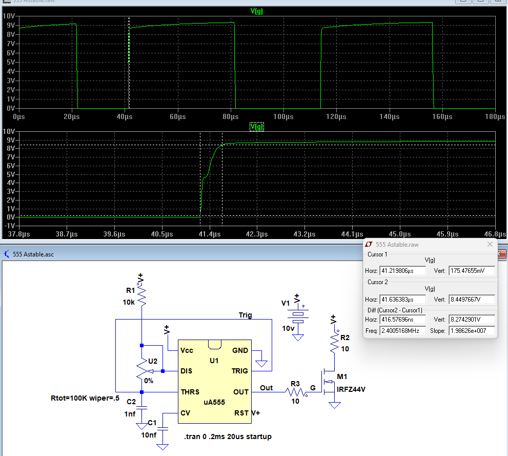
The IRFZ44 has a total gate charge of 63nC. The 555 output can source at least 100mA of current. This gives a rise-time of 63nC/100mA = 630ns which should rapidly turn on the MOSFET.
For maximum rise-time use no more than 10Ω in series with the gate.
Here is the LTspice sim of a 555 driving the MOSFET. It shows a rise-time of <500ns.
-
1\$\begingroup\$ Minimum* but yes, and the output saturates to high enough voltage that the MOSFET will be safely on; hence the remaining tail can be ignored. \$\endgroup\$ Commented Nov 7 at 20:25


