0
\$\begingroup\$

I'm bad at electronics. I have to create a circuit which, after a normally-closed switch is opened, sends a signal (could be high or low) to a microcontroller and, after approximately 1 second, drives an Enable Not pin of a motor driver (TMC2209) high.

I came out with the following circuit: circuit
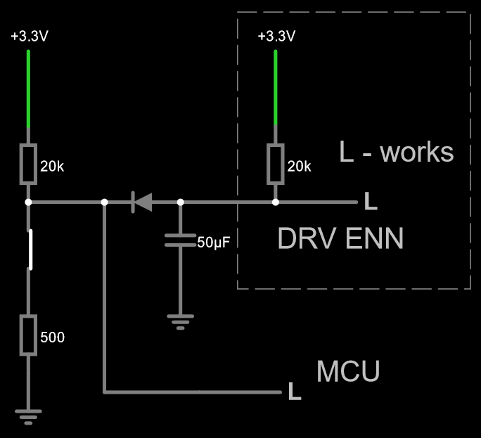
The diode is for keeping the delay caused by the capacitor in the DRV portion. I can't change what's in the rectangle, I'm working with a pre-made module. 500ohm resistor is for discharging the capacitor. Pull-up above the switch is for quickly driving MCU input high.

It works in the simulator, but would it work in the real world? From other questions I saw that the RC delay circuits aren't very good and a 555 timer would be better, but it's definitely more complex.

\$\endgroup\$
2
  • 2
    \$\begingroup\$ You have an MCU. Is there a reason you can't use the MCU to detect button, and separately let the MCU drive the enable after a software delay? This will not change what's inside a rectangle, and slowly changing signals are bad on logic inputs. \$\endgroup\$
    – Justme
    Commented Nov 14 at 23:37
  • \$\begingroup\$ The normally closed switch will be an e-stop. The signal to mcu is for stopping the machine, the delay on enable is for cutting of power. I want to avoid the mcu to have the least software innput, plus I'm low on pins and can't upgrade to a bigger one. If the slow rising signals are bad, then 555 I guess, but are they really that bad? There is a Schmitt trigger on enable. \$\endgroup\$
    – Radar32
    Commented Nov 15 at 0:04

3 Answers 3

0
\$\begingroup\$

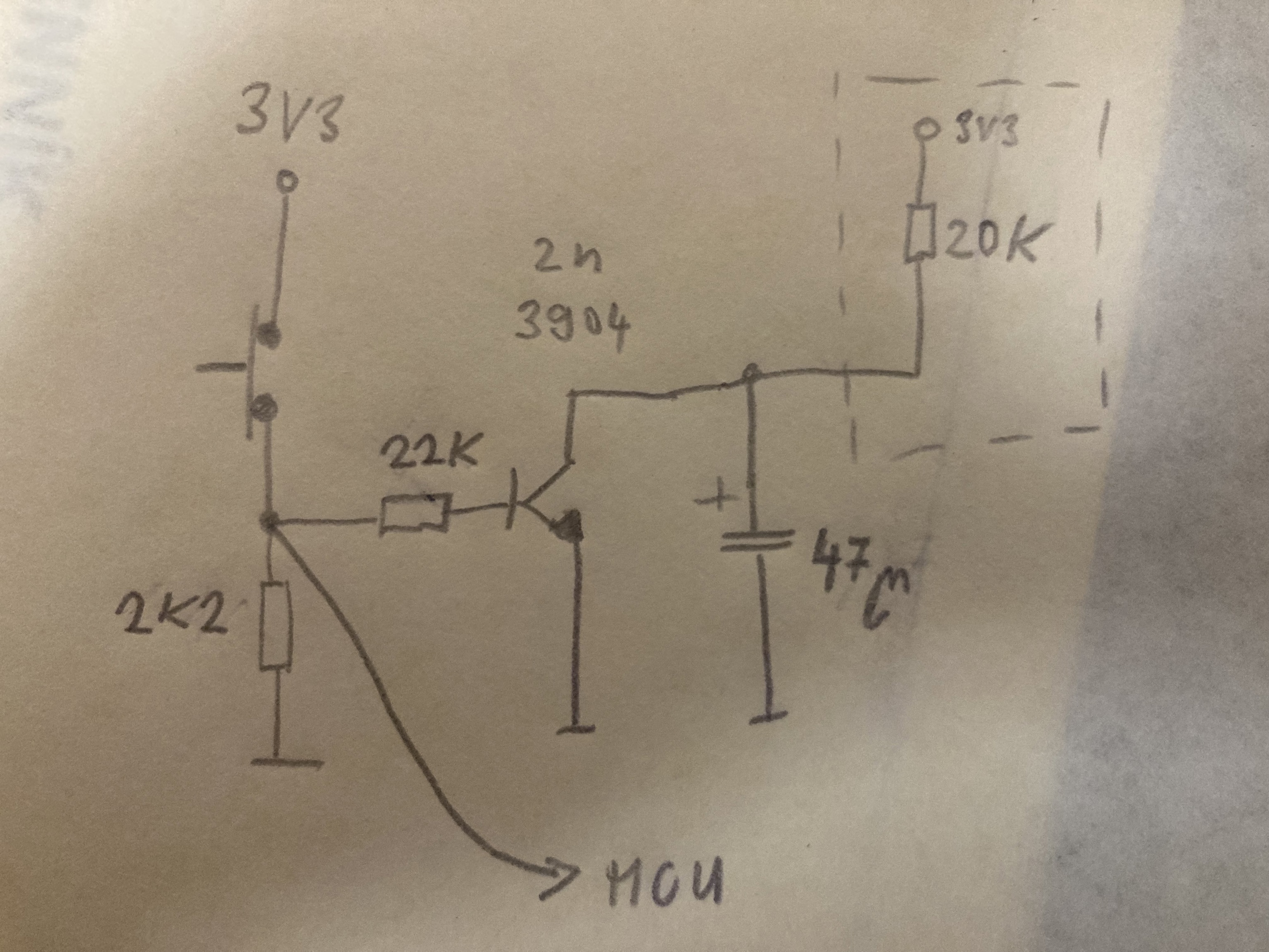
Since you work with small 3v3 voltage the diode has a huge impact how deep the cap is discharged and affects the timing. So I would use a transistor instead.

Here the discharging resistor is not needed. The 22k in base will limit the transistor (the cap discharging) current to few mA only.

enter image description here

\$\endgroup\$
1
  • \$\begingroup\$ The MCU signal is the wrong logic polarity. It should go high when the switch is open. \$\endgroup\$
    – AnalogKid
    Commented Nov 15 at 2:59
0
\$\begingroup\$

If you are sure that the DRV ENN input is a Schmitt trigger, then what you have should work. In the switch-closed state, the DRV ENN signal will be over 0.8 V because of the two 20 K resistors feeding the 500 ohm resistor. This might be too high to assure a logic 0 state at the input. Changing the diode to a small-signal Shottkey should assure a valid low signal, but be sure to verify this with a prototype build before committing to production.

\$\endgroup\$
0
\$\begingroup\$

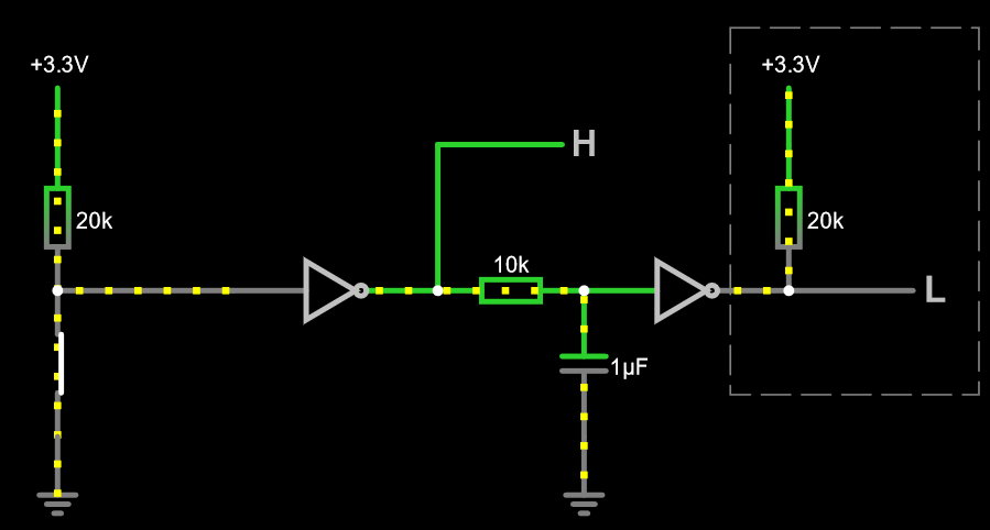
Thank you @AnalogKid and @Michal Podmanický, but I found a different solution. I'm going to use this simple circuit:

circ

I've taken the inspiration from the Art of Electronics. They use buffers, but NOT gates are cheaper. It has the advantage of protecting both the input signal from the capacitor and the capacitor from the output. Without the second NOT I'd have to solve some voltage divider equations. The first NOT gate charges and discharges the capacitor.

\$\endgroup\$
3
  • \$\begingroup\$ I assume the NOT gates will be a type with a Schmitt-trigger input, otherwise the output of the second gate could oscillate when the relatively slow RC output is near the input threshold. \$\endgroup\$ Commented Nov 16 at 13:48
  • \$\begingroup\$ I agree. Only use gates that have schmitt trigger inputs, or you will be violating input slew rate specs for any normal gate. \$\endgroup\$
    – Justme
    Commented Nov 16 at 14:18
  • \$\begingroup\$ Yep, they have Schmitt trigger \$\endgroup\$
    – Radar32
    Commented Nov 16 at 18:12

Your Answer

By clicking “Post Your Answer”, you agree to our terms of service and acknowledge you have read our privacy policy.

Not the answer you're looking for? Browse other questions tagged or ask your own question.