2
\$\begingroup\$

I have yj61 series motor. Something like this
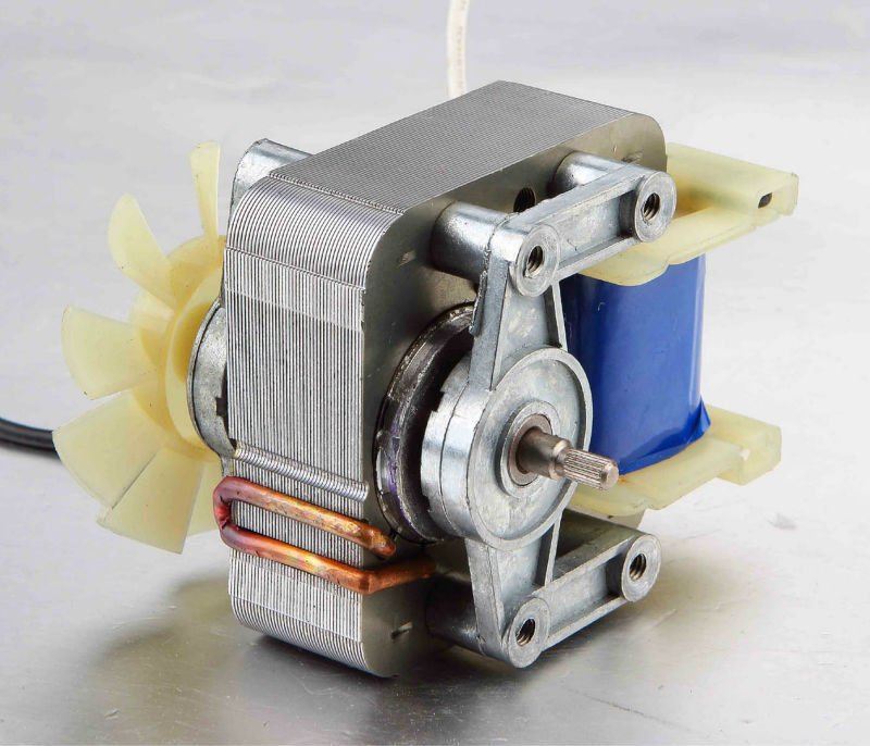
enter image description here

It's rated AC120V 60Hz 3000RPM and was damaged by accidental connection to 220v mains. I can't find suitable spare motor, so I have to rewind this one anyway.

And if I have to rewind it, then I'm curious if it is possible to change its winding to make it 3000rpm at 220V 50Hz, to remove 220v-110v transformer from the setup.

Could you provide me with book reference or any other material which explains how to calculate coil parameters for shaded pole motors? Ready to use answers (like "use doubled number of turns with a half-diameter wire") are welcome too.

\$\endgroup\$
3
  • 1
    \$\begingroup\$ Double number of turns would be right, but you want to half the area of the wire. or 1/sqrt(2) the diameter. \$\endgroup\$
    – user16324
    Commented Nov 25, 2013 at 16:59
  • \$\begingroup\$ Thank you, Brian. If I double number of turns, then new wire will be more than twice longer compared to original. And if I at the same time half the area of the new wire, then impedance of the new winding will be more than four times of the original. I guess, that it doesn't really matter, because active impedance of the wire provide only the small part of the full impedance of coil. Right? \$\endgroup\$ Commented Nov 25, 2013 at 18:23
  • \$\begingroup\$ @AlexLaskin Any idea why there is a blue tape around the coil? \$\endgroup\$
    – Mark Messa
    Commented Mar 19, 2019 at 12:46

2 Answers 2

4
\$\begingroup\$

Double number of turns would be right, but you want to half the area of the wire. or 1/sqrt(2) the diameter.

New wire should be about twice as long. (More turns fit on a layer, and each layer is thinner so the next layer is smaller than the original). How close you get to this depends on how well you wind (and how well the original was!)

Impedance will then be 4x the original, which is expected : at twice the voltage, for the same power, you draw half the current, so the power loss hasn't changed.

It looks as if there's plenty of room on the bobbin, so use the next wire guage up if you can't find an exact one, and that'll bring the resistances back down.

It's not clear exactly what you mean by "the active impedance of the wire" but in a running motor, only a small percentage of the AC supply actually causes current flow in the coil; the remainder is cancelled out by the "back EMF" from the rotor acting as a generator. (Until you stall the motor...)

Finally, if your 220V supply is 50Hz rather than 60Hz, expect the motor to draw more power than intended; it may not be running fast enough to generate the back-EMF it was designed for. I can't suggest how to adjust the turns ratio for that case.

\$\endgroup\$
1
  • \$\begingroup\$ Any idea why there is a blue tape around the coil? \$\endgroup\$
    – Mark Messa
    Commented Mar 19, 2019 at 12:46
2
\$\begingroup\$

Doubling the number of turns and halving the wire area (which is approximately equivalent to an increase by 3 wire gauges, by the way) will get you close if all you are doing is changing voltage. But as Brian pointed out this doesn't account for the change in frequency.

Lower frequency means a slower speed, so your motor won't spin at 3000 RPM - probably closer to 2500 RPM. So if your application requires 3000 RPM, then running on 50 Hz probably isn't a good idea. Slower speeds also means that the fan on your rotor will be spinning at a lower speed so it won't cool as well. This could cause the motor to overheat if you are trying to use the same load as when it was running at 60 Hz. Another issue is that when frequency decreases, so does your V/Hz ratio. This ratio is important because if you keep it constant, then you also keep the flux in the magnetic circuit of the motor constant. If the frequency decreases, however, the current in the motor will increase in current and an increase in flux density. This could cause the magnetic core to saturate. If this is the case you may want to take a few turns out of the winding to compensate for the lower frequency. How many you take out depends on the original winding and the shape of the laminations. The goal would be to get the flux density back as close as possible to the original 120 V,60 Hz flux density.

\$\endgroup\$
2
  • \$\begingroup\$ It's worth noting that fans have a quadratic speed-torque curve, which is to say that the airflow goes down as the square of the speed. Running a fan at 5/6ths its rated speed will result in only 70% of the airflow. \$\endgroup\$ Commented Nov 30, 2013 at 10:46
  • \$\begingroup\$ Any idea why there is a blue tape around the coil? \$\endgroup\$
    – Mark Messa
    Commented Mar 19, 2019 at 12:46

Your Answer

By clicking “Post Your Answer”, you agree to our terms of service and acknowledge you have read our privacy policy.

Not the answer you're looking for? Browse other questions tagged or ask your own question.