1
\$\begingroup\$

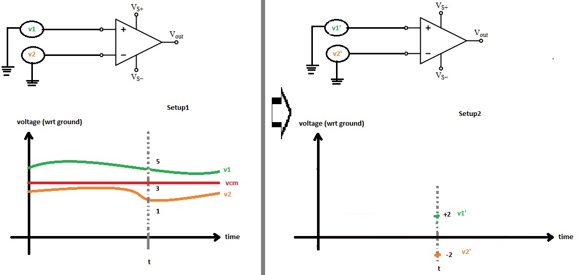
I was struggling to understand what common mode voltage and CMRR is. I think eventually I understand what it is about. Before posing my new question I will briefly write about my drawing. On the left side in setup 1 varying v1 and v2 with respect to ground are applied as inputs of a differential amplifier. And at time "t" v1=5V and v2=1V. It means the amplifier will reject (5+1) / 2 = 3V common-mode voltage (at time t) and take the signals as +2V and -2V inputs (vd = 4V difference).

Differential amplifier schematic

In setup 2 (kind of equivalent to setup 1) at time "t" v1'= +2V and v2'=-2V are applied as inputs of a differential amplifier. Similarly in this case vd = 4V potential difference between the inputs. But because in this case the common-mode voltage vcm=0 it looks like this measurement is more accurate because even it is non-ideal amplifier (having a common mode gain) it will not affect output voltage because vcm=0.

If I have a sensor like a strain gauge which setup is realistic in real life? In data acquisition systems when they use differential inputs instead of single inputs does that correspond to setup 2? Will v1 and v2 always at any time t be as such v1=-v2? I'm a bit confused relating to the real scenario.

\$\endgroup\$
1
  • \$\begingroup\$ You mention a strain gauge which outputs 10mV; for this kind of application you want an instrumentation amplifier. \$\endgroup\$
    – pjc50
    Commented Dec 6, 2013 at 13:27

3 Answers 3

4
\$\begingroup\$

You seem to be suffering from a common misunderstanding about what actually makes differential inputs useful. When we have differential inputs, what we really care about is that the impedances of each half of the differential pair are balanced.

Too many descriptions of this sort of circuit illustrate a differential input with two signals, with equal magnitude but opposite polarity, which isn't wrong, but it fails to draw attention to how these circuits actually work. Example:

plot of differential signal

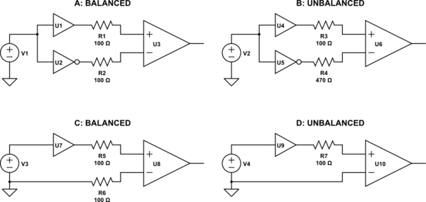
Notice that the input signal is fed into two buffers, one of them inverting. You can do this, and indeed this is a balanced signal, but it's not because the voltage on the "-" input is inverted: it's because (ostensibly) the two buffers used here have equal output impedances, and the input impedances on the differential amplifier are equal. Here are some more examples:

schematic

simulate this circuit – Schematic created using CircuitLab

Although both A and B have voltages at the differential amplifier's input that are equal in magnitude but opposite in phase, B is not balanced. This is because the line impedances (set by R3 and R4) are not equal. When this differential line is subjected to noise from an external source, unequal voltages will be induced on each half of the differential pair, and thus noise will not be common mode, and will not be rejected by the differential amplifier.

On the other hand, D depicts a typical case of a single-ended, ground-referenced signal. D is not balanced either, because again the impedances are not equal. However, C presents the same voltages to the differential input, yet C is balanced, because the impedances are equal. Although the signal (represented by V3) is not "centered" on ground, and the resulting voltages at U8 contain the signal in differential mode, plus half the signal in common mode, this is still balanced. The signal is still amplified, and noise is still rejected, which is just what you want.

As far as what you will encounter in practice, the answer is you may encounter either. Each of A and C can be made to work well, depending on the application's requirements. (What range of frequencies? How much dynamic range is necessary?) If you understand why differential amplifiers are useful, and what a balanced signal really is, you will realize that the common mode voltage at the receiver inputs doesn't matter.

\$\endgroup\$
10
  • \$\begingroup\$ Input impedance in a "typical" one op-amp differential amplifier, even if packaged as a unit with laser trimmed resistors, are not the same for the two inputs. \$\endgroup\$ Commented Dec 6, 2013 at 13:31
  • 1
    \$\begingroup\$ @ScottSeidman did I say something to the contrary? \$\endgroup\$
    – Phil Frost
    Commented Dec 6, 2013 at 13:45
  • \$\begingroup\$ "what we really care about is that the input impedances are balanced". They're not on what many would call a differential amplifier, which can still have a fine CMRR. \$\endgroup\$ Commented Dec 6, 2013 at 13:48
  • \$\begingroup\$ @ScottSeidman sure, if you can find a way to make induced noise common mode, which you can't, which is why when we want to implement a good differential amplifier from real op-amps, we use an instrumentation amplifier. \$\endgroup\$
    – Phil Frost
    Commented Dec 6, 2013 at 13:50
  • \$\begingroup\$ I agree, there's a place for in-amps, and a place for difference amps, both of which are differential amplifiers. Both are available as stand-alone IC's. I'm just pointing out there are differences, and we should be a bit careful about lumping them together for discussion, or people will walk away with the idea that difference amps have cruddy CMRR, when they don't. \$\endgroup\$ Commented Dec 6, 2013 at 14:00
0
\$\begingroup\$

Short answer: Inputs \$V_1\$ and \$V_2\$ to the amplifier produces an output voltage that is a function of \$ V_1 - V_2\$. Now, suppose you increase both of the input voltages by exactly one volt, that is, raise the common mode voltage by 1V. In an ideal amplifier, the output voltage is unchanged, but in an actual amplifier, it might change just a tiny amount. This output voltage change is the CMRR.

\$\endgroup\$
4
  • \$\begingroup\$ yes but thats not my question. \$\endgroup\$
    – user16307
    Commented Dec 5, 2013 at 23:46
  • \$\begingroup\$ Sorry. I was trying to help with your first statement, "I was struggling to understand what common mode voltage and CMRR is." I'm not sure that you understand it if you are wondering whether V1 has to equal -V2 \$\endgroup\$
    – user28910
    Commented Dec 5, 2013 at 23:53
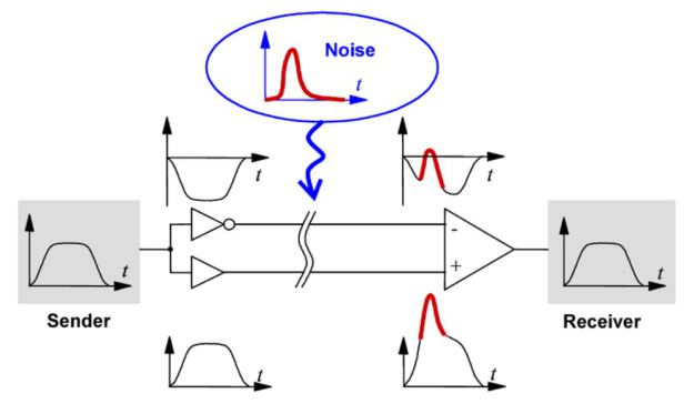
  • \$\begingroup\$ Could u look at this Figure: ueidaq.files.wordpress.com/2013/11/… also inputs arranges such as v1=-v2. Whats that about? – \$\endgroup\$
    – user16307
    Commented Dec 5, 2013 at 23:55
  • \$\begingroup\$ The figure illustrates the technique of differential signalling for common mode noise rejection. It shows noise that is coupled into both inputs (ie common mode noise) rejected by the receiver, which cares only about the difference between its inputs. This is a common method for transmitting information, both analog and digital, over distances where the signal may be corrupted by noise, differences in ground reference, etc. Of course, V1 could be equal to -V2, but usually it's not done that way because (1) it requires an additional negative supply on both ends and (2) its not necessary. \$\endgroup\$
    – user28910
    Commented Dec 6, 2013 at 13:16
0
\$\begingroup\$

In all but the most sensitive applications, the common-mode gain of a differential amplifier is so small it can be considered to be zero. Usually there are other sources of noise that are a bigger problem.

However, you also seem to be wondering if care is usually taken to keep the common-mode voltage at zero. The answer is: usually not.

It's quite reasonable to have a "differential" signal where one of the voltages is always 0V, and the other is the signal. This isn't really different from an ordinary ground-referenced voltage signal (not differential), except when you treat it as differential, you also imply that you are taking care to make the impedances of both inputs equal. If you don't do this, then induced noise won't be common-mode, and there's little point then in using a differential amplifier.

For an example, consider this balanced audio line driver:

schematic (from Elliott Sound Products, I suggest you read the article. This is actually a very common design in professional audio equipment.)

Pin 2 and pin 3 are designed to go into a differential receiver on the other end. However you will notice that pin 3 is always 0V. You will also notice that it is connected through ground through R3, which exists to make the impedance of this signal equal to the op-amp's output impedance, which is set by R2.

If we just connect pin 3 directly to ground, then the voltages output look the same, but we don't have "balanced" audio, because the impedances of pin2 and pin3 will not be equal, and noise picked up by the cable will not be common mode, and can't be rejected by the receiver on the other end.

If you think about it, this sends a differential-mode signal, but it also sends a common-mode signal that is always half the differential-mode signal. That is, if we want to output 5V, then:

$$ \begin{align} V_{pin2} &= 5V\\ V_{pin3} &= 0V\\ V_{dm} &= 5V\\ V_{cm} &= 2.5V \end{align}$$

That there's also a common-mode voltage doesn't really matter. Most of it will be rejected by the receiver on the other end anyway, and what little remains isn't noise, because it's the same as the signal. Any common-mode gain on the receiver just gets added to the differential-mode gain. Of course, if the receiver has poor common-mode rejection it will be poor at rejecting noise, but that our line driver is also injecting some common-mode signal doesn't make it any worse.

Again, the important thing is this: for differential signals, keep the impedances equal. The rest is distraction.
\$\endgroup\$
13
  • \$\begingroup\$ One of my question is: In a data acquisition system when we connect the sensor as differential ended inputs does that mean at a time t v1 = -v2 with respect to ground? If so how is that achieved? \$\endgroup\$
    – user16307
    Commented Dec 5, 2013 at 23:25
  • \$\begingroup\$ @user16307 no, it doesn't mean that. The audio line driver here could just as well be a strain gauge or any other sensor. There's no requirement for v1=-v2. The requirement is that the impedances are equal, at least if you want the benefits of noise rejection that differential measurement can provide. \$\endgroup\$
    – Phil Frost
    Commented Dec 5, 2013 at 23:28
  • \$\begingroup\$ latticesemi.com/~/media/Documents/ApplicationNotes/… could u check this? what abut V- and V+ there? isn't that v1 = -v2 situation? \$\endgroup\$
    – user16307
    Commented Dec 5, 2013 at 23:31
  • 2
    \$\begingroup\$ @user16307 it is, but notice this part: "Although not necessary, the average of the two voltages will often remain the same." That V1 = -V2 in their examples is a distraction. It is not a requirement of differential signaling and doesn't degrade performance at all. People naturally like thinking of it this way because it makes everything "balanced" and "symmetrical", and because they can't imagine the fulcrum of that see-saw moving up and down as it tips such that one of the riders never moves up or down. But actually, you can do this, and it works fine. \$\endgroup\$
    – Phil Frost
    Commented Dec 5, 2013 at 23:38
  • \$\begingroup\$ lets say i have a sensor and without amplification the potential difference between its 2 outputs is 10mV. I want to amplify this signal using differential ended method should I use 2 differential amplifier? \$\endgroup\$
    – user16307
    Commented Dec 5, 2013 at 23:42

Your Answer

By clicking “Post Your Answer”, you agree to our terms of service and acknowledge you have read our privacy policy.

Not the answer you're looking for? Browse other questions tagged or ask your own question.