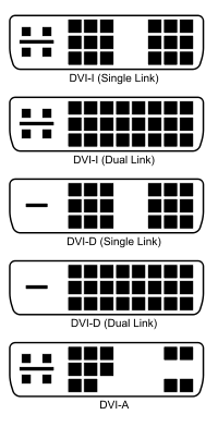
The Wikipedia page about DVI connectors contains quite a bit of information on the variants. After a quick look at the table on the right of that table I can't see any obvious ones that could be safely skipped depending on the variant(s) you're using, so it would probably be easiest to assume you'll need to connect every pin from the following diagram:

I've only soldered a DVI connector once for a repair and it wasn't too bad, although I have a good soldering iron and quite a bit of soldering experience. A lot of high density round connectors come into the same category, they're not too bad to hand-solder but do take some care and it can be fairly tedious connecting them.
Another thing to remember is that a lot of the signals have return paths that should either be shielded or formed as twisted pairs. Over a short distance you may get away with ignoring that, but unless you're careful you may spend a lot of time on it and then discover it has a negative on the image quality, radiates noise that gets into other devices or doesn't work at all.
One simple "get it done and it'll work" method that comes to mind is placing a hole large enough in the bottom of your shell casing to pass a standard connector through and run a couple of short slots up the side. I assume you'll be mounting it upright so you won't see the larger holes in the bottom and can run them out the slots on the side. You could also make up a brass cover plate to make it all look neater.

