1
\$\begingroup\$

I am learning electronics on my own and I have a feeling a capacitor can solve an issue I have.

The datasheet for a part, which is powered by three lines (+12V, 0V, -12V) says that it draws 40 mA continuusouly, but that it can also draw up to 250 mA temporarily, for 0.1 second.

Well, let's say I just cannot afford to put on my board a power supply capable of giving 250 mA (I can go up to 80 mA). Can I use a capacitor to help supply the temporary surge?

I have thought of :

Capacity required : 0.250 * 0.1 = 0.0250 A.s (Coulombs) Let's say I decide to connect the capacity to the +12V and -12V (is it ok ? Should I have two or three capacitors ?), then, with a 50 V capacity, that makes :

0.0250 / 50 = 0.0005 F

So I would need a 500 µF capacity to do the job. Is that correct ?

But then, when the part draws 250 mA for 0.1 s, the capacity get discharged, and it temporarily draws more current on the power source to recharge. I can solve this using a resistor, but where to put it, and how to choose it?

I have thought of that :

schematic

simulate this circuit – Schematic created using CircuitLab

OR
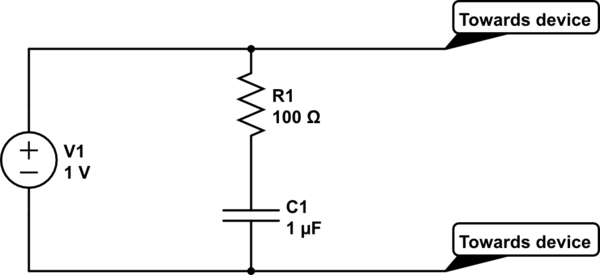
schematic

simulate this circuit

What do you think ? Is it even a good solution ?

\$\endgroup\$
3
  • \$\begingroup\$ What is the part? If it draws every other 0.1 second say, that has to be factored in. \$\endgroup\$ Commented Jan 1, 2014 at 14:29
  • \$\begingroup\$ It is a 4-20 mA current loop reciever. So I would expect it to only occasionnaly draw that much current (thought I do not understand why it would). \$\endgroup\$
    – PeterG
    Commented Jan 1, 2014 at 15:18
  • \$\begingroup\$ What is the part? (part number and link to datasheet??) This isn't really making sense yet. Is it a loop powered transmitter or what? \$\endgroup\$ Commented Jan 1, 2014 at 18:49

1 Answer 1

2
\$\begingroup\$

You're sort of on the right track, but you can't just put 50V across your capacitor without also putting 50V across your circuit, which would probably damage it.

I would start by saying that you probably want two capacitors, one between +12V and ground, and the other between -12V and ground.

Then, you need to decide how much you can allow each of the 12V buses to "sag" during the current surge. For example, if you could tolerate a 2V drop during the surge, then the capacitance needed would be 0.025 C / 2 V = 0.0125 F, or 12500 µF.

The resistor — if needed at all — should be positioned as shown in your first diagram, in series with the source, not in series with the capacitor. But the power source's built-in current limiting will probably be sufficient without the need for another resistor.

\$\endgroup\$
1
  • 1
    \$\begingroup\$ The situation is a bit better if you assume that the power supply continues to provide 80mA while the capacitor is discharging. Then you need 0.017C or a measly 0.0085F. \$\endgroup\$
    – Joe Hass
    Commented Jan 1, 2014 at 16:18

Your Answer

By clicking “Post Your Answer”, you agree to our terms of service and acknowledge you have read our privacy policy.

Not the answer you're looking for? Browse other questions tagged or ask your own question.