I have this breadboard and I have started experimenting with pic micros. In doing so I have needed a 5 volt power supply. I have seen several tutorials for wiring up 5 volt regulator circuits on a breadboard, however when I try to hook up the 7805 on the breadboard, the 7805 will not fit on the breadboard. With extra force I can force it on the breadboard, but I assumed this would damage the breadboard. What is a common solution to this problem?
-
\$\begingroup\$ You could try chipping off the extra lead, but it's probably fine to apply some force to it though. \$\endgroup\$– PyxzureCommented Jan 29, 2014 at 2:00
-
1\$\begingroup\$ In my experience, jamming the leads of a TO-220 into a breadboard doesn't damage it enough to be a concern. \$\endgroup\$– Nick AlexeevCommented Aug 16, 2014 at 21:14
6 Answers
You could solder #22 or #24 wire to the 7805 leads, then poke those wires into thte breadboard.
Alternatively, build the voltage regulator on some perfboard (or just solder things together in mid-air), rather than trying to put the 7805 on the plastic breadboard.
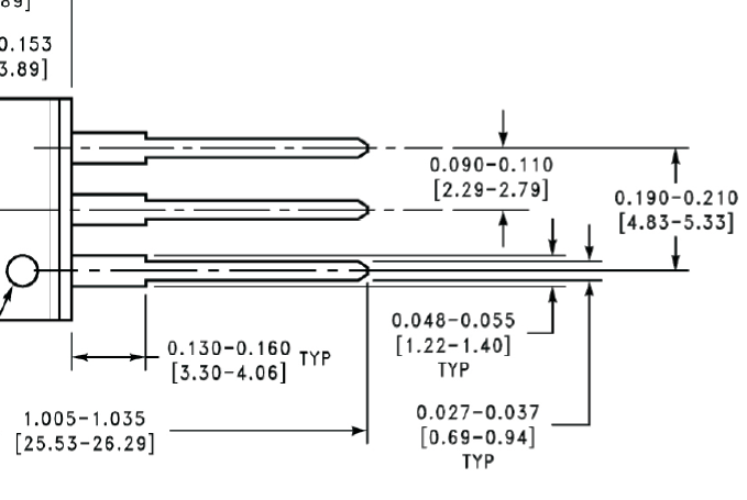
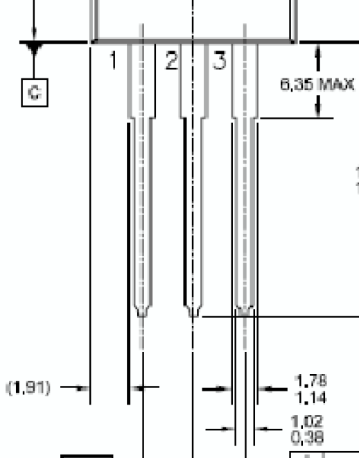
If you look carefully at the data sheet drawings, some have wider leads than others.
TI LM341/78M05

Fairchild LM78M05

A typical maximum diameter for a solderless breadboard is 0.91mm (AWG 19), so the Fairchild part will be too big, whereas the TI part will probably fit fine.
-
\$\begingroup\$ -1 But he already has the 7805, he's not looking for shopping advice. \$\endgroup\$– Joe HassCommented Jan 29, 2014 at 3:44
-
1\$\begingroup\$ Shopping is finding a sound aubergine at the market. Design is specifying a part that will work and will fit the holes you have to use. \$\endgroup\$ Commented Jan 29, 2014 at 4:02
-
\$\begingroup\$ Again, the OP already has a 7805 in hand and wants to adapt it to a breadboard. He is not specifying a part for a new design. \$\endgroup\$– Joe HassCommented Jan 29, 2014 at 17:54
-
\$\begingroup\$ Seems your interpretation of his question is far more literal and rigid than mine. Oh, well, can't please everyone. \$\endgroup\$ Commented Jan 29, 2014 at 19:26
I wouldn't put them directly on a breadboard since it might be damaged due to the too thick pins of most TO-220 components.
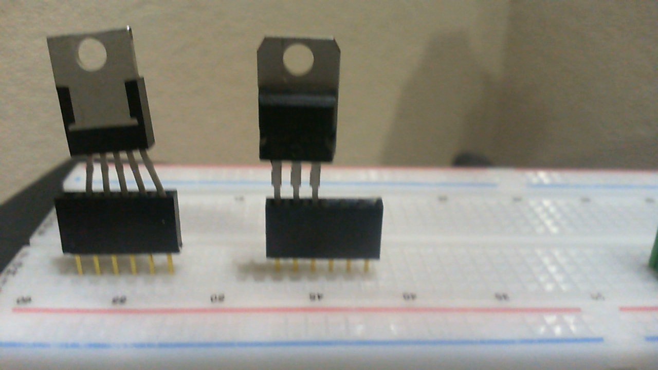
Instead, use a male-female pin header. You can easily stuck a 3 pin 7805 in a pin header (with a bit of force) and place it easily in a breadboard. This way the breadboard does not get broken and a pin header is very cheap in case you damage one. You can buy them even in 3 or 5 holes width so they fit perfectly.
I also tried a 5 pin LM2576 HVT and after bending the pins and checking the conductivity with a digital multi meter I can confirm it works fine too.
Just twist the three legs of the regulator (90 degrees) using pliers.
I just plug them in.
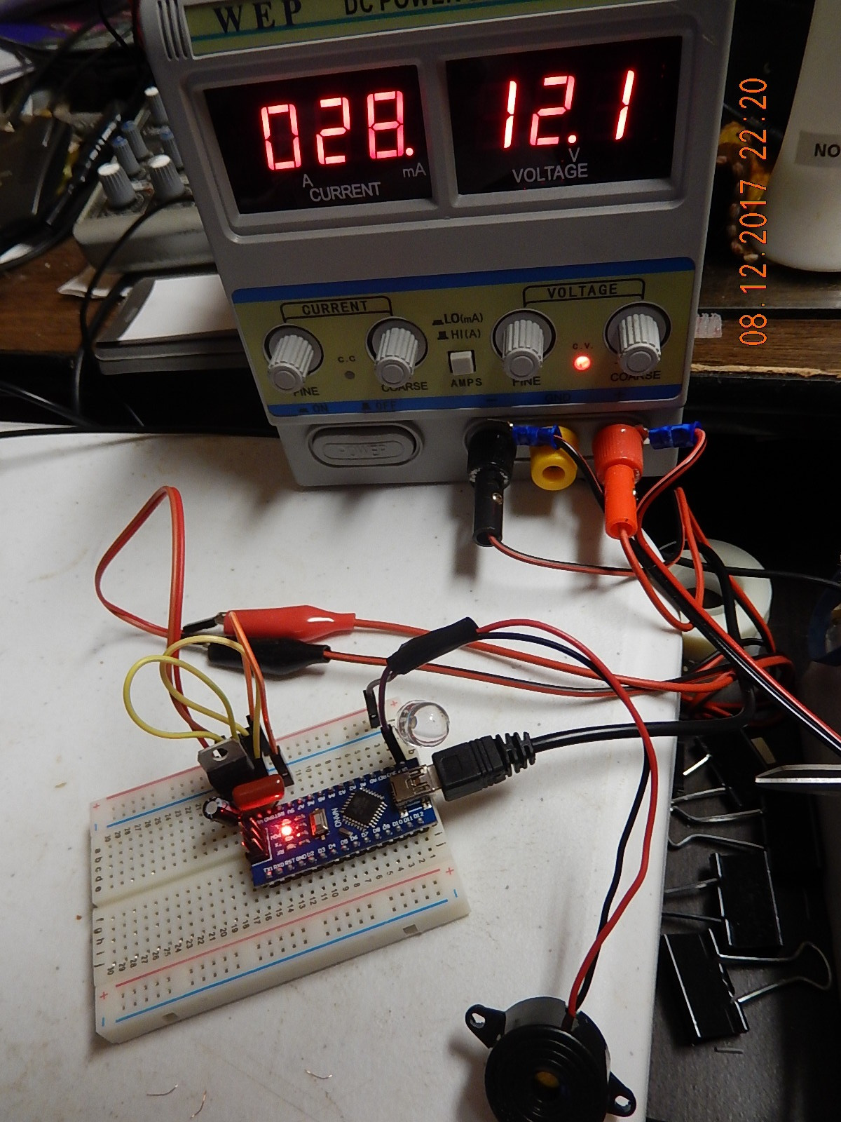
Here is a photo of a 7809 taking in 12V with a .1 uF electrolytic on the input, then a non-electrolytic .33 uF across gnd and Vin of an Arduino Nano.
Due to the pinouts of the 7809 the closest yellow wire bridges the gnd between the 7809 and the Nano gnd pin, and the cap is right at the Nano itself.
Nice, stable circuit that doesn't have any trouble with doing analog readings. (I measure the voltage on Vref for the equations)
You could try using a blank piece of protoboard or perfboard like Peter suggested, and solder up some standard spaced headers (https://www.sparkfun.com/products/116) to the regulator, then use that on the breadboard.
Those headers should easily fit into the breadboard.


