13
\$\begingroup\$

I have a very old phone (60 years old) and I want to control its part using a Raspberry PI:

  • Microphone & speaker from the head set
  • The bell
  • The dial wheel

I have the electric circuit but don't recognise all of the parts.
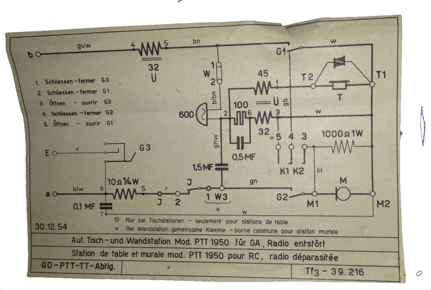
enter image description here

My question is now how I can achieve the following using the Raspberry PI:

  1. Detect the signal from the dial wheel
  2. Ring the bell
  3. Use the microphone and the speakerphone from the headset
  4. Detect when the headset was liftet from the hook

Additionally I don't understand all parts in the circuit:

e.g. what is this Pulse Icon is with the caption of 100 between 2 and 6

Update

I tried to decipher the circuit in order to be able to use the hardware of this phone. I used blue for the German color codes of my cables and green for the connectors:
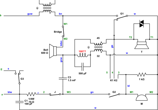
schematic

simulate this circuit – Schematic created using CircuitLab

On the phone I have the following connectors:

  • M1: Microphone (red)
  • M2: Microphone (pink)
  • T1: Speaker (dark green)
  • T2: Speaker (light green)
  • a: Phone line?
  • b: Phone line?
  • E: Phone line?
  • W1 + W2 (bridged)
  • W3/1: green cable connected n times with red through J when dialled
  • 2: red
  • 3: blue
  • 4: yellow
  • 5: white

Update 2:

It sais 300 Ohm - 7000 W - 0.13 Ku Em on the two coils, which are used for the bells.

This is the acutal phone on the inside.
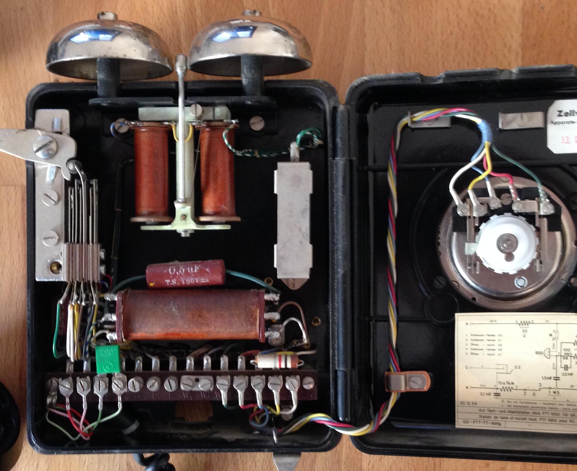
enter image description here

\$\endgroup\$
5
  • \$\begingroup\$ Have you tried looking for adapters? Like analog phone to isdn? Might be easier for the PI to talk to the ISDN chip then? \$\endgroup\$
    – user36598
    Commented Feb 3, 2014 at 17:26
  • 1
    \$\begingroup\$ I want to use it without any actual phone line. I just want to use the hardware. So I might use it as a sound recorder. Anything really.... \$\endgroup\$
    – Besi
    Commented Feb 3, 2014 at 17:35
  • \$\begingroup\$ I suspect the 'pulse icon' thing is a thermistor, to compensate for different telephone line lengths. The 'diac' like thing across the earpiece would be some sort of surge suppresion to protect the user's ear from transients and signals above a specific voltage. \$\endgroup\$
    – peterG
    Commented Feb 3, 2014 at 23:48
  • 1
    \$\begingroup\$ @Wilhelmsen thanks. I know, it is really beautiful. It's the one I grew up with so I am really attached to it and bringing it back to life is like travelling back in time. The phone was built in 1956. \$\endgroup\$
    – Besi
    Commented Feb 5, 2014 at 14:01
  • \$\begingroup\$ I have achieved this - inspired by the SparkFun one. I have decoded the pulse dial of the rotary and the hook status into the inputs of the Raspberry Pi - see this link for more details. It was great fun making it and was fairly easy to write the Python code to control it. On thing I did find though is that you can't hold it and pay for coffee at the same time! \$\endgroup\$
    – user39631
    Commented Apr 1, 2014 at 20:07

5 Answers 5

5
\$\begingroup\$

Take a look at this: https://www.sparkfun.com/tutorials/51 . They reverse engineered a rotary phone similar to yours. If you want some more detailed answers, you're going to have to explain exactly what you don't understand about the schematic.

\$\endgroup\$
4
\$\begingroup\$

In order to control a telephone set like this you will probably need to "deconstruct" it down to its essential functional components. Each of these components will then be easier to deal with than trying to use the set as a whole in the original way it was meant to be connected to the two-conductor telephone system. "Deconstruct" means unwire the whole thing and just use the earpiece on its own, the dial one its own, the mic on it's own, etc.

The dial is simply a cam driven switch. Put an ohm meter across its wires and you will be able to see it operate. You dial a "1" you get one pulse (switch contacts open and close), you dial a "2" you get 2 pulses. The "0" gives you ten pulses.

The headphone is usually a magnetic coil arrangement with an impedance of 300-600 ohms. You can drive this from a simple sub-1-watt audio amplifier. Don't worry about the impedance mismatch, these things were poor audio quality!

The microphone is a carbon mic and requires that you pass a DC current thru it to get an AC voice signal out of it. If you hook up a AA battery and a 470 Ohm resistor in series with it and connect an O-scope between the resistor and mic you will see the voice signal.

The bell is probably the biggest challenge you will face. It takes a lot of voltage at a certain frequency to get it to ring properly. The bell coil assembly is mechanically resonant at a certain frequency. So you need to drive it at that frequency (usually around 30 Hz) to get it to sound properly. Originally, the telephone systems ran on 48 VDC, so that's what the bell was designed for. You may get away with a lesser voltage if you get the drive frequency correct. You'll have to experiment a bit with a signal generator and a beefy audio amplifier to determine the correct frequency to use. There were a number of standard frequencies, but they were all between 20 & 50 Hz. You want to find the frequency at which the bell sounds the loudest. Because that is the resonant frequency of the coil mechanism, that will also be the frequency which requires the least energy ( volts and amps) to drive it.

Good Luck!

\$\endgroup\$
2
  • \$\begingroup\$ Actually the ringers run off around 90v AC superimposed on top of the 48v DC line current. In the US, the typical frequency is 20 Hz. I can't tell if this is a German or Fench phone as both languages appear on the schematic. In France, the ringing frequency is 50 Hz at 80v AC. Elsewhere in Europe, 25 Hz is commonly used. You could generate the proper ringing frequency using a sine table lookup inside the Raspberry Pi and use that to drive gate controlling a high-voltage output. Or you could build a circuit using a 555 timer and then just turn it on and off using the Raspberry Pi. \$\endgroup\$
    – tcrosley
    Commented Feb 3, 2014 at 15:41
  • \$\begingroup\$ You could also look at making the bell a self-oscillating one, where the movement of the arm breaks the circuit to the coil. \$\endgroup\$
    – John U
    Commented Feb 3, 2014 at 15:44
3
\$\begingroup\$

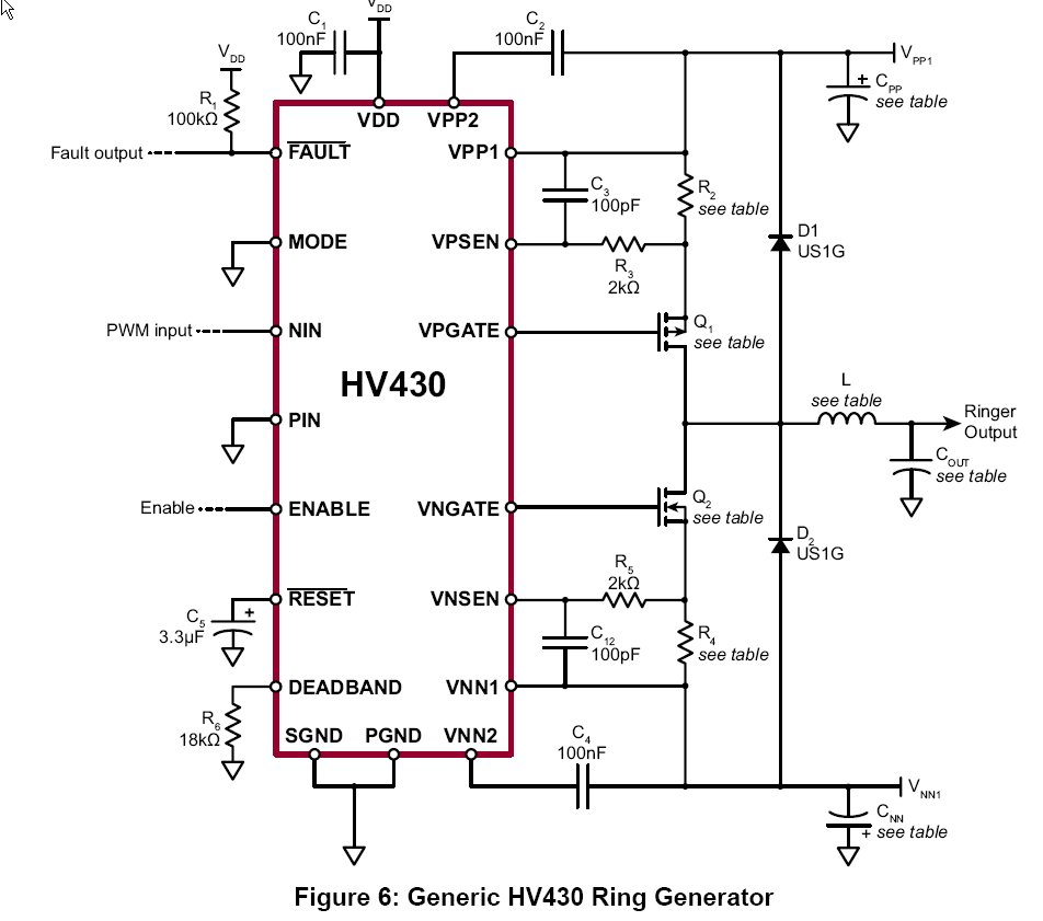
For generating the ring, there are special high-voltage ICs designed just for this task.

One example is the Supertex HV430.

enter image description here

\$\endgroup\$
4
  • \$\begingroup\$ Interesting chip, where is it available? (Not listed at Digi-Key or Newark, Non-stock status at Mouser.) \$\endgroup\$
    – tcrosley
    Commented Feb 3, 2014 at 17:29
  • \$\begingroup\$ onlinecomponents.com has 414 in stock at 6.54 each, there might be a later chip from Supertex. \$\endgroup\$ Commented Feb 3, 2014 at 18:02
  • \$\begingroup\$ Thanks, never heard of them, always nice to find a new supplier. \$\endgroup\$
    – tcrosley
    Commented Feb 3, 2014 at 18:24
  • \$\begingroup\$ I have used them uneventfully. No other connection to them. \$\endgroup\$ Commented Feb 3, 2014 at 18:26
3
\$\begingroup\$

Personally, I'm horrified by the amount of suggestions to break the excellent piece of phone classic. People pay good money for this things. :)

One more constructive approach is to hook up the phone in question with a special adapter, like those listed here:

http://www.voip-info.org/wiki/view/Dial+Pulse+to+Touchtone+DTMF+Converters

(VoIP adapters that can run pulse dialing phones directly, also exist: http://www.oldphoneworks.com/xlink-cellular-bluetooth-gateway-bttn-version.html)

The resulting DTMF-compatible line can then be hooked to a small and cheap VoIP box (plenty of those around); in turn, VoIP box can be trivially controlled over the network by any sort of scriptable SIP server (including recording and remote control purposes, not necessary telephony). One popular and very scriptable option is good old Asterisk:

http://www.raspberry-asterisk.org/

\$\endgroup\$
2
\$\begingroup\$

Your best bet is to modify the phone itself into component parts, and attach each element to an appropriate circuit driven by the Raspberry PI. The bell will need about 90VAC 20Hz to ring. The microphone and speaker should be obvious. The dialer and hook can be left together and connected to another input which you'll have to monitor for dialing pulses and hook events.

If you cannot modify the phone, what you need to do is build an FXO (foreign exchange office) interface. There are several existing FXO<-->USB adaptors on the market, most fairly inexpensive, which will do everything you need except the dialing. You could add a small circuit in parallel with the phone to monitor the line and catch the dialing separate from the FXO interface. It will probably be easier than building an entire interface yourself.

A compromise between completely modifying the phone and using an existing external interface would be to disconnect the dialer from the circuit, and add a pulse to tone conversion circuit inside the phone. This would not only enable you to use an off the shelf FXO to USB interface, but it would also allow you to connect the phone, as-is, to any modern telephony network.

Building the entire interface yourself isn't that hard, though. It's just that the phone combines 5 functions on two wires, and you're essentially building 5 different circuits to handle each function. It would be best if you broke this question up into several more questions for each function (perhaps combine the speaker and mic into one question).

\$\endgroup\$

Your Answer

By clicking “Post Your Answer”, you agree to our terms of service and acknowledge you have read our privacy policy.

Not the answer you're looking for? Browse other questions tagged or ask your own question.