I'm going to answer your second question first: we call something "small signal" when it is small signal enough for our purposes. No matter what, electronic amplifiers distort. You can't get rid of it -- you can just work harder and make it smaller. So if you're involved in a structured design process, you decide ahead of time how much distortion you'll accept, and you design (and test) to that.
This distortion may be expressed as THD if it's an audio amplifier, or some sort of intermodulation distortion if it's RF, or as a total nonlinearity error if it's some sort of measurement device (presumably going into an ADC). I'm sure there are other measures that I'm unaware of -- but they all boil down to answering the question "is this amplifier linear enough?".
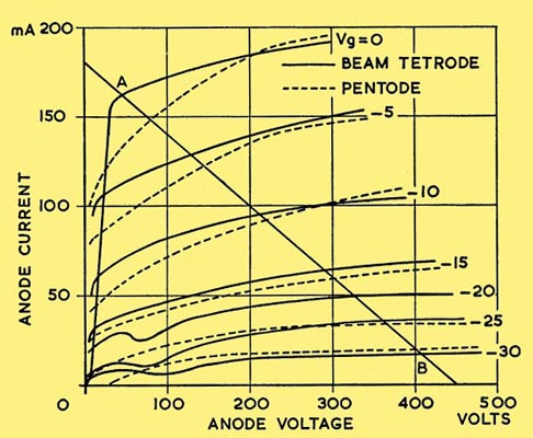
For your first question, I'm going to be self-indulgent and use a load line for a pentode (vacuum tube) amplifier rather than a transistor. I hope it doesn't confuse things too much, but I just like tubes. The principle is the same though -- you could replace the tube characteristic with a MOSFET or even a BJT and get essentially the same thing.
The center of the load line, from the \$V_g = 0\mathrm{V}\$ plate line to the \$V_g = -30\mathrm{V}\$ plate line, happens at around 230V on the plate, and \$V_g = -12\mathrm{V}\$ or so.
There are two reasons that you can see, by inspection, that using the full plate voltage swing does not result in small-signal operation: first, because you can, by visual inspection, see that the plate current vs. grid voltage curve is "squashed" as the grid voltage gets more negative. This effect happens with both FETs and BJTs. The second reason that you can see, by inspection, that using the full swing isn't small signal any more is because the center grid voltage between \$V_g = 0\mathrm{V}\$ and \$V_g = -30\mathrm{V}\$ is \$V_g = -15\mathrm{V}\$, not \$-12\mathrm{V}\$.
This effect is even more pronounced with transistors, which is why tube amps can often get by without feedback.


