2
\$\begingroup\$

common-source amplifier

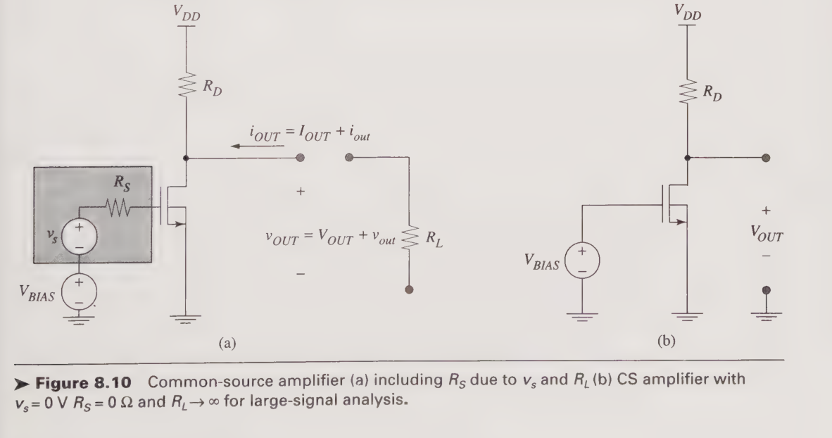
I'm currently studying electronic devices. I've reached transistor amplifiers. The image above shows a common-source amplifier. I'm confused about why the textbook takes the load out for DC analysis. Won't the analysis be invalid after we connect the load back, wont conditions, eg, output voltage, change due to the re-connection of \$R_L\$? The textbook talks about how \$V_{BIAS}\$ vs \$V_{OUT}\$ is such that at about \$V_{DD}/2\$ the small-signal gain is the highest, using a plot that they present, which is fine, but how do I connect the open-circuit behaviour to the case where \$R_L\$ is actually there?

Edit: The image comes from page 475 of the following book,

title: "Microelectronics: An integrated approach"
authors: "Roger T. Howe & Charles G. Sodini"
publisher: "Prentice Hall"
ISBN: "9780135885185"

\$\endgroup\$
4
  • 1
    \$\begingroup\$ Think about the Thevenin equivalent of this circuit. Let's say you were to represent it with a voltage source in series with a resistor. How would you go about calculating that voltage? \$\endgroup\$
    – a360pilot
    Commented Nov 11 at 8:28
  • \$\begingroup\$ What output load voltage do you want to have when the input signal is zero. \$\endgroup\$
    – Andy aka
    Commented Nov 11 at 8:31
  • \$\begingroup\$ @a360pilot How can I get a thevenin equivalent of a non-linear device? Isn't thevenin applicable in only linear networks? \$\endgroup\$ Commented Nov 11 at 8:33
  • \$\begingroup\$ @Andy the textbook recommends halfway between Vdd & ground, because apparently, that's where the slope of the Vout vs Vbias curve is the highest, so small signal gain is the highest. But that curve is in open circuit conditions, I don't understand how it relates to when R_L is present \$\endgroup\$ Commented Nov 11 at 8:36

1 Answer 1

1
\$\begingroup\$

What output load voltage do you want to have when the input signal is zero?

@Andy the textbook recommends halfway between Vdd & ground

When the input signal is zero, the voltage across the output load is also zero and, no load current flows. This assumes that you have set-up the DC quiescent biasing point to be mid-rail at the collector/drain (normal for this type of amplifier). And, that the load resistor is biased with an offset voltage of half Vdd.

Under these circumstances you should be able to see that the load resistor does not affect the DC analysis because it draws zero current. This means that you can remove \$R_L\$ because it doesn't affect the DC quiescent bias conditions.

Alternatively you can consider \$R_L\$ to be grounded and connected to \$V_{OUT}\$ via a coupling capacitor because that has the same effect.

The bottom line is that the DC operating conditions are analysed with zero signal inputted and, it is expected that any load connected will not draw current.

\$\endgroup\$
3
  • \$\begingroup\$ Does a voltage source V_dd/2 need to be in series with R_L? If so, I think I understand this answer, otherwise im confused \$\endgroup\$ Commented Nov 11 at 10:02
  • \$\begingroup\$ @YeslinSequeira yes it does. Sorry I wasn't clearer. The quiescent condition is achieved with a signal input of zero volts producing an output signal of zero volts hence, the load resistor must be have a voltage source of half Vdd in series with it. \$\endgroup\$
    – Andy aka
    Commented Nov 11 at 10:05
  • \$\begingroup\$ Ok, that makes perfect sense to me. The textbook wasnt explicit about it, so I was confused. Thanks for the answer! \$\endgroup\$ Commented Nov 11 at 10:08

Your Answer

By clicking “Post Your Answer”, you agree to our terms of service and acknowledge you have read our privacy policy.

Not the answer you're looking for? Browse other questions tagged or ask your own question.