0
\$\begingroup\$

Behzad Razavi in his book mentions

It is important to bear in mind that small signal analysis deals with only (small) changes in voltages and currents around their quiescent values.... If the signal perturbs the bias point of the device only negligibly, we say the circuit operates in the small signal regime. So the change in Icq due to the signal must remain small.

However when we study about maximum symmetrical swing we look to bias it by the middle of the ac load line.. So the if the collector bias current is Icq then the maximum swing too is Icq. But.. How then is the change in Icq, small, due to application of signal????? How do we specify the small signal regime of operation?

\$\endgroup\$
1
  • 1
    \$\begingroup\$ you need to think about how much distortion you can accept, then craft a Taylor Series to provide the coefficients for the distortion, and determine your pain level. I think Willie Sansen has an article on bipolar transistor distortion. \$\endgroup\$ Commented Aug 17, 2019 at 4:04

4 Answers 4

1
\$\begingroup\$

I'm going to answer your second question first: we call something "small signal" when it is small signal enough for our purposes. No matter what, electronic amplifiers distort. You can't get rid of it -- you can just work harder and make it smaller. So if you're involved in a structured design process, you decide ahead of time how much distortion you'll accept, and you design (and test) to that.

This distortion may be expressed as THD if it's an audio amplifier, or some sort of intermodulation distortion if it's RF, or as a total nonlinearity error if it's some sort of measurement device (presumably going into an ADC). I'm sure there are other measures that I'm unaware of -- but they all boil down to answering the question "is this amplifier linear enough?".

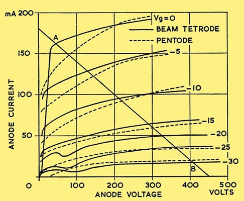
For your first question, I'm going to be self-indulgent and use a load line for a pentode (vacuum tube) amplifier rather than a transistor. I hope it doesn't confuse things too much, but I just like tubes. The principle is the same though -- you could replace the tube characteristic with a MOSFET or even a BJT and get essentially the same thing.

The center of the load line, from the \$V_g = 0\mathrm{V}\$ plate line to the \$V_g = -30\mathrm{V}\$ plate line, happens at around 230V on the plate, and \$V_g = -12\mathrm{V}\$ or so.

There are two reasons that you can see, by inspection, that using the full plate voltage swing does not result in small-signal operation: first, because you can, by visual inspection, see that the plate current vs. grid voltage curve is "squashed" as the grid voltage gets more negative. This effect happens with both FETs and BJTs. The second reason that you can see, by inspection, that using the full swing isn't small signal any more is because the center grid voltage between \$V_g = 0\mathrm{V}\$ and \$V_g = -30\mathrm{V}\$ is \$V_g = -15\mathrm{V}\$, not \$-12\mathrm{V}\$.

This effect is even more pronounced with transistors, which is why tube amps can often get by without feedback.
enter image description here

\$\endgroup\$
2
\$\begingroup\$

How then is the change in Icq "small? due to application of signal????? How do we specify the small signal regime of operation?

"Small signal" and "large signal" do not represent different "regimes of operation". They are two different analysis techniques used to evaluate the design of a circuit, and they are used in unrelated areas.

Large signal analysis is used to determine things like bias points and maximum output swing. Small signal analysis linearizes the circuit so that other aspects such as frequency response are easier to estimate.

\$\endgroup\$
3
  • 1
    \$\begingroup\$ I think you worded it better than I did – this upvote is yours. It's also worth mentioning that whatever is small or large, significant or insignificant is in the end defined by the constraints given for a model that the engineer uses. So, basically, things like these are found through modelling. \$\endgroup\$ Commented Aug 16, 2019 at 16:11
  • \$\begingroup\$ So the maximum output swing we find out.. They are the limit for "large" input excursions.. Is it? \$\endgroup\$
    – nn08
    Commented Aug 16, 2019 at 16:13
  • \$\begingroup\$ @Nullbyte as said: however you model your device. Typically, you'll define a "small-scale model" with operating boundaries, and a "large-scale model" with operating boundaries. the latter doesn't have to cover all the "possible" out- and inputs of the device. \$\endgroup\$ Commented Aug 16, 2019 at 16:18
1
\$\begingroup\$

Exactly like the author you cite:

If the signal perturbs the bias point of the device only negligibly

"Negligibly" is a term defined by what you do with the device. There can't be a general answer!

So, you need to consider the operation with "small signals" as part of the operation within the full, "large signal" range of the device, not separately.

\$\endgroup\$
2
  • \$\begingroup\$ Something that bugged me again.. If for a large amplifier gain and "small" input swings we get "large" swings in collector current.. Can we still employ small signal analysis techniques? My problem here is that within the large collector current swings, the ic-vbe curve encompasses non-linearity.. So how do we work around with the gm of the device.. I can't wrap my head around this tiny bit \$\endgroup\$
    – nn08
    Commented Aug 17, 2019 at 3:45
  • 1
    \$\begingroup\$ you're really missing the point: without you defining what your small-scale model is, and what errors in modelling you accept, there's nothing to reason about. \$\endgroup\$ Commented Aug 17, 2019 at 8:09
1
\$\begingroup\$

How do we specify the small signal regime of operation?

The definition depends on the application.

The small signal regime is when we operate the system with small enough signals that the error we get by using small signal analysis, rather than full nonlinear analysis, is not "too much". "Too much" means more error than we can accept for whatever purpose we are using our analysis or simulation results.

So the if the collector bias current is Icq then the maximum swing too is Icq. But.. How then is the change in Icq, small, due to application of signal?

The reason we chose to bias the transistor with the collector current in the middle of the load line is so that we could achieve the maximum swing without causing large non-linearities due to entering the saturation regime of the transistor.

As long as we don't see the large non-linearities due to saturation, the response might be "close enough" to linear for many purposes. There will still be some small non-linearities that result in small(ish) harmonic distortion of our signal, but these might not be important for determining the output amplitude or the highest frequency our circuit can pass, for example, to an acceptable degree of accuracy.

\$\endgroup\$

Your Answer

By clicking “Post Your Answer”, you agree to our terms of service and acknowledge you have read our privacy policy.

Not the answer you're looking for? Browse other questions tagged or ask your own question.