4
\$\begingroup\$

I'm studying the multilevel flying capacitor inverter topologies. I simulated a five-level model on Simulink and the results are OK, but when doing the simulation in LTspice with MOSFET models (IRF830) I don't get the same results, and the simulation takes a long time to run.

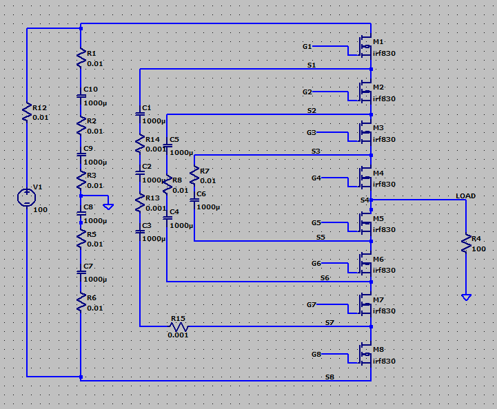
I tried adding the parasitic series/parallel resistors on the capacitors and voltage source but no change. The design I implemented was as follows:

This is the MOSFETs stage: enter image description here

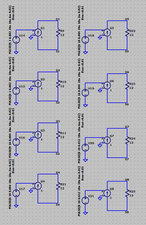
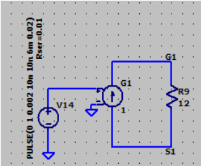
This is the control stage: enter image description here

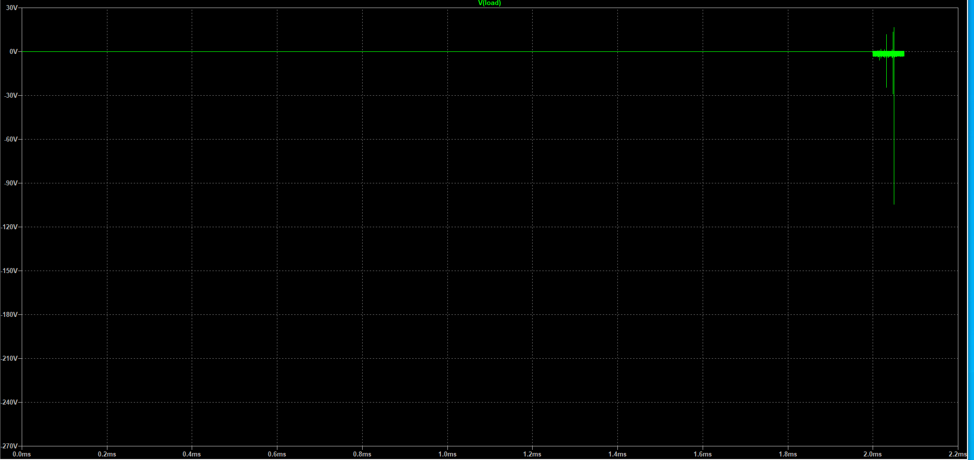
This is the waveform on the load resistor (the simulation stops at this point and does not progress):

enter image description here

The implementation I did in Simulink is as follows: enter image description here
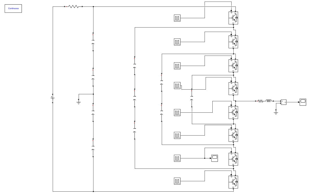
And the output of the above simulation is: enter image description here
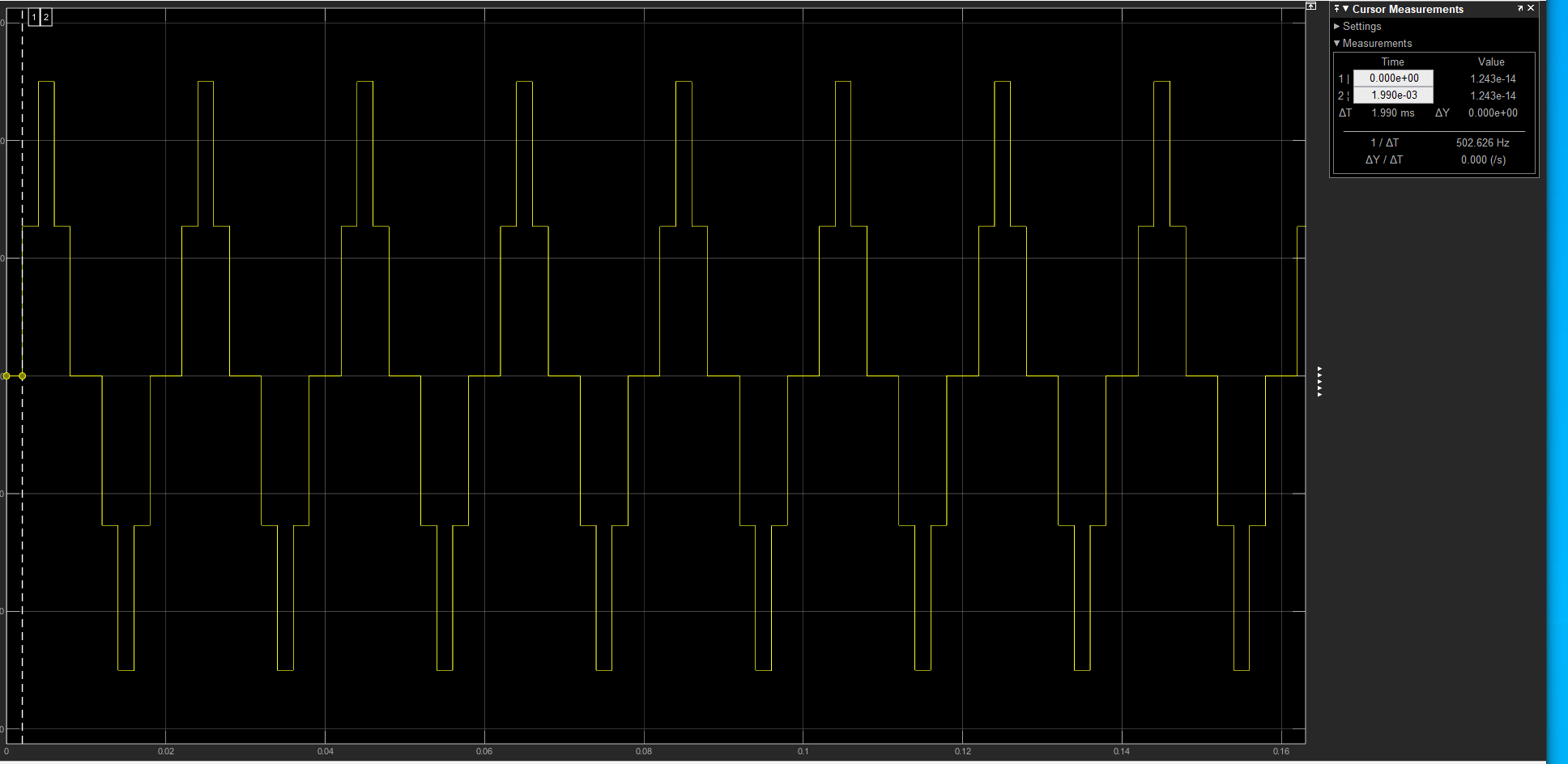
I also checked that the gate signals of the MOSFETs were correct in LTspice and in Simulink. I found no differences.

Here are the simulation files for LTspice:

Version 4
SHEET 1 5220 3772
WIRE 224 -1136 48 -1136
WIRE 832 -1136 656 -1136
WIRE 48 -1072 48 -1136
WIRE 224 -1072 224 -1136
WIRE 656 -1072 656 -1136
WIRE 832 -1072 832 -1136
WIRE 0 -1056 -144 -1056
WIRE 608 -1056 464 -1056
WIRE -144 -1008 -144 -1056
WIRE 0 -1008 -16 -1008
WIRE 464 -1008 464 -1056
WIRE 608 -1008 592 -1008
WIRE -16 -992 -16 -1008
WIRE 592 -992 592 -1008
WIRE 48 -880 48 -992
WIRE 224 -880 224 -992
WIRE 224 -880 48 -880
WIRE 656 -880 656 -992
WIRE 832 -880 832 -992
WIRE 832 -880 656 -880
WIRE -144 -864 -144 -928
WIRE 464 -864 464 -928
WIRE 224 -688 48 -688
WIRE 832 -672 656 -672
WIRE 48 -624 48 -688
WIRE 224 -624 224 -688
WIRE 0 -608 -144 -608
WIRE 656 -608 656 -672
WIRE 832 -608 832 -672
WIRE 608 -592 464 -592
WIRE -144 -560 -144 -608
WIRE 0 -560 -16 -560
WIRE -16 -544 -16 -560
WIRE 464 -544 464 -592
WIRE 608 -544 592 -544
WIRE 592 -528 592 -544
WIRE 48 -432 48 -544
WIRE 224 -432 224 -544
WIRE 224 -432 48 -432
WIRE -144 -416 -144 -480
WIRE 656 -416 656 -528
WIRE 832 -416 832 -528
WIRE 832 -416 656 -416
WIRE 464 -400 464 -464
WIRE 4816 -256 3792 -256
WIRE 224 -240 48 -240
WIRE 3792 -240 3792 -256
WIRE 3792 -240 3600 -240
WIRE 4816 -224 4816 -256
WIRE 832 -192 656 -192
WIRE 48 -176 48 -240
WIRE 224 -176 224 -240
WIRE 3792 -176 3792 -240
WIRE 4736 -176 4608 -176
WIRE 0 -160 -144 -160
WIRE 4736 -144 4736 -176
WIRE 4768 -144 4736 -144
WIRE 656 -128 656 -192
WIRE 832 -128 832 -192
WIRE -144 -112 -144 -160
WIRE 0 -112 -16 -112
WIRE 608 -112 464 -112
WIRE -16 -96 -16 -112
WIRE 4608 -96 4000 -96
WIRE 4816 -96 4816 -128
WIRE 4816 -96 4608 -96
WIRE 464 -64 464 -112
WIRE 608 -64 592 -64
WIRE 4816 -64 4816 -96
WIRE 592 -48 592 -64
WIRE 3792 -32 3792 -96
WIRE 4736 -16 4608 -16
WIRE 48 16 48 -96
WIRE 224 16 224 -96
WIRE 224 16 48 16
WIRE 3600 16 3600 -240
WIRE 4736 16 4736 -16
WIRE 4768 16 4736 16
WIRE -144 32 -144 -32
WIRE 4000 32 4000 -96
WIRE 656 64 656 -48
WIRE 832 64 832 -48
WIRE 832 64 656 64
WIRE 3792 64 3792 32
WIRE 4608 64 4096 64
WIRE 4816 64 4816 32
WIRE 4816 64 4608 64
WIRE 464 80 464 16
WIRE 4816 80 4816 64
WIRE 4000 128 4000 96
WIRE 4736 128 4624 128
WIRE 4096 144 4096 64
WIRE 4736 160 4736 128
WIRE 4768 160 4736 160
WIRE 3792 176 3792 144
WIRE 224 208 48 208
WIRE 4624 208 4192 208
WIRE 4816 208 4816 176
WIRE 4816 208 4624 208
WIRE 4000 240 4000 208
WIRE 4192 240 4192 208
WIRE 4816 240 4816 208
WIRE 3792 256 3792 240
WIRE 48 272 48 208
WIRE 224 272 224 208
WIRE 832 272 656 272
WIRE 4096 272 4096 208
WIRE 0 288 -144 288
WIRE 4736 288 4640 288
WIRE 3600 320 3600 96
WIRE 4736 320 4736 288
WIRE 4768 320 4736 320
WIRE -144 336 -144 288
WIRE 0 336 -16 336
WIRE 656 336 656 272
WIRE 832 336 832 272
WIRE 4000 336 4000 304
WIRE 4192 336 4192 320
WIRE -16 352 -16 336
WIRE 608 352 464 352
WIRE 3792 352 3792 336
WIRE 3888 352 3792 352
WIRE 4816 368 4816 336
WIRE 5152 368 4816 368
WIRE 3792 384 3792 352
WIRE 3888 384 3888 352
WIRE 464 400 464 352
WIRE 608 400 592 400
WIRE 4096 400 4096 352
WIRE 4816 400 4816 368
WIRE 592 416 592 400
WIRE 4816 416 4816 400
WIRE 3792 448 3792 432
WIRE 4000 448 4000 416
WIRE 4736 448 4640 448
WIRE 48 464 48 352
WIRE 224 464 224 352
WIRE 224 464 48 464
WIRE 3792 464 3792 448
WIRE -144 480 -144 416
WIRE 4736 480 4736 448
WIRE 4768 480 4736 480
WIRE 5152 480 5152 368
WIRE 4192 512 4192 400
WIRE 4640 512 4192 512
WIRE 4816 512 4816 496
WIRE 4816 512 4640 512
WIRE 656 528 656 416
WIRE 832 528 832 416
WIRE 832 528 656 528
WIRE 464 544 464 480
WIRE 4816 544 4816 512
WIRE 3792 592 3792 544
WIRE 4736 592 4640 592
WIRE 4736 624 4736 592
WIRE 4768 624 4736 624
WIRE 4096 656 4096 464
WIRE 4656 656 4096 656
WIRE 4816 656 4816 640
WIRE 4816 656 4656 656
WIRE 3792 688 3792 656
WIRE 4816 688 4816 656
WIRE 5152 704 5152 560
WIRE 4736 736 4624 736
WIRE 4736 768 4736 736
WIRE 4768 768 4736 768
WIRE 4000 816 4000 512
WIRE 4096 816 4000 816
WIRE 4672 816 4176 816
WIRE 4816 816 4816 784
WIRE 4816 816 4672 816
WIRE 4816 864 4816 816
WIRE 4736 912 4640 912
WIRE 4736 944 4736 912
WIRE 4768 944 4736 944
WIRE 3600 992 3600 400
WIRE 3792 992 3792 768
WIRE 3792 992 3600 992
WIRE 3792 1008 3792 992
WIRE 4672 1008 3792 1008
WIRE 4816 1008 4816 960
WIRE 4816 1008 4672 1008
FLAG 5152 368 LOAD
FLAG 5152 704 0
FLAG 3888 384 0
FLAG 4608 -96 S1
FLAG 4608 64 S2
FLAG 4624 208 S3
FLAG 4816 368 S4
FLAG 4640 512 S5
FLAG 4656 656 S6
FLAG 4672 816 S7
FLAG 4672 1008 S8
FLAG -16 -992 0
FLAG -144 -864 0
FLAG 224 -1136 G1
FLAG 224 -880 S1
FLAG -16 -544 0
FLAG -144 -416 0
FLAG 224 -688 G2
FLAG 224 -432 S2
FLAG -16 -96 0
FLAG -144 32 0
FLAG 224 -240 G3
FLAG 224 16 S3
FLAG -16 352 0
FLAG -144 480 0
FLAG 224 208 G4
FLAG 224 464 S4
FLAG 592 -992 0
FLAG 464 -864 0
FLAG 832 -1136 G5
FLAG 832 -880 S5
FLAG 592 -528 0
FLAG 464 -400 0
FLAG 832 -672 G6
FLAG 832 -416 S6
FLAG 592 -48 0
FLAG 464 80 0
FLAG 832 -192 G7
FLAG 832 64 S7
FLAG 592 416 0
FLAG 464 544 0
FLAG 832 272 G8
FLAG 832 528 S8
FLAG 4608 -176 G1
FLAG 4608 -16 G2
FLAG 4624 128 G3
FLAG 4640 288 G4
FLAG 4640 448 G5
FLAG 4640 592 G6
FLAG 4624 736 G7
FLAG 4640 912 G8
SYMBOL res 5136 464 R0
SYMATTR InstName R4
SYMATTR Value 100
SYMBOL voltage 3600 304 R0
WINDOW 123 0 0 Left 0
WINDOW 39 0 0 Left 0
SYMATTR InstName V1
SYMATTR Value 100
SYMBOL res 3776 -192 R0
SYMATTR InstName R1
SYMATTR Value 0.01
SYMBOL res 3776 48 R0
SYMATTR InstName R2
SYMATTR Value 0.01
SYMBOL res 3776 240 R0
SYMATTR InstName R3
SYMATTR Value 0.01
SYMBOL res 3776 448 R0
SYMATTR InstName R5
SYMATTR Value 0.01
SYMBOL res 3776 672 R0
SYMATTR InstName R6
SYMATTR Value 0.01
SYMBOL res 3584 0 R0
SYMATTR InstName R12
SYMATTR Value 0.01
SYMBOL cap 3984 32 R0
SYMATTR InstName C1
SYMATTR Value 1000µ
SYMATTR SpiceLine Rser=0.01 Rpar=100meg
SYMBOL cap 3984 240 R0
SYMATTR InstName C2
SYMATTR Value 1000µ
SYMATTR SpiceLine Rser=0.01 Rpar=100meg
SYMBOL cap 3984 448 R0
SYMATTR InstName C3
SYMATTR Value 1000µ
SYMATTR SpiceLine Rser=0.01 Rpar=100meg
SYMBOL cap 4080 400 R0
SYMATTR InstName C4
SYMATTR Value 1000µ
SYMATTR SpiceLine Rser=0.01 Rpar=100meg
SYMBOL cap 4080 144 R0
SYMATTR InstName C5
SYMATTR Value 1000µ
SYMATTR SpiceLine Rser=0.01 Rpar=100meg
SYMBOL cap 4176 336 R0
SYMATTR InstName C6
SYMATTR Value 1000µ
SYMATTR SpiceLine Rser=0.01 Cpar=100meg
SYMBOL res 4176 224 R0
SYMATTR InstName R7
SYMATTR Value 0.01
SYMBOL res 4080 256 R0
SYMATTR InstName R8
SYMATTR Value 0.01
SYMBOL g 48 -1088 R0
SYMATTR InstName G1
SYMATTR Value 1
SYMBOL voltage -144 -1024 R0
WINDOW 3 -53 -243 VRight 2
WINDOW 123 0 0 Left 0
WINDOW 39 -25 -243 VRight 2
SYMATTR InstName V14
SYMATTR Value PULSE(0 1 0.002 10n 10n 6m 0.02)
SYMATTR SpiceLine Rser=0.01
SYMBOL res 208 -1088 R0
SYMATTR InstName R9
SYMATTR Value 12
SYMBOL g 48 -640 R0
SYMATTR InstName G2
SYMATTR Value 1
SYMBOL voltage -144 -576 R0
WINDOW 3 -53 -243 VRight 2
WINDOW 123 0 0 Left 0
WINDOW 39 -25 -243 VRight 2
SYMATTR InstName V15
SYMATTR Value PULSE(0 1 0.002 10n 10n 6m 0.02)
SYMATTR SpiceLine Rser=0.01
SYMBOL res 208 -640 R0
SYMATTR InstName R10
SYMATTR Value 12
SYMBOL g 48 -192 R0
SYMATTR InstName G3
SYMATTR Value 1
SYMBOL voltage -144 -128 R0
WINDOW 3 -53 -243 VRight 2
WINDOW 123 0 0 Left 0
WINDOW 39 -25 -243 VRight 2
SYMATTR InstName V16
SYMATTR Value PULSE(0 10 0.004 10n 10n 2m 0.02)
SYMATTR SpiceLine Rser=0.01
SYMBOL res 208 -192 R0
SYMATTR InstName R11
SYMATTR Value 12
SYMBOL g 48 256 R0
SYMATTR InstName G4
SYMATTR Value 1
SYMBOL voltage -144 320 R0
WINDOW 3 -53 -243 VRight 2
WINDOW 123 0 0 Left 0
WINDOW 39 -25 -243 VRight 2
SYMATTR InstName V17
SYMATTR Value PULSE(0 10 0.004 10n 10n 2m 0.02)
SYMATTR SpiceLine Rser=0.01
SYMBOL res 208 256 R0
SYMATTR InstName R21
SYMATTR Value 12
SYMBOL g 656 -1088 R0
SYMATTR InstName G5
SYMATTR Value 1
SYMBOL voltage 464 -1024 R0
WINDOW 3 -53 -243 VRight 2
WINDOW 123 0 0 Left 0
WINDOW 39 -25 -243 VRight 2
SYMATTR InstName V18
SYMATTR Value PULSE(0 10 0.004 10n 10n 2m 0.02)
SYMATTR SpiceLine Rser=0.01
SYMBOL res 816 -1088 R0
SYMATTR InstName R22
SYMATTR Value 12
SYMBOL g 656 -624 R0
SYMATTR InstName G6
SYMATTR Value 1
SYMBOL voltage 464 -560 R0
WINDOW 3 -53 -243 VRight 2
WINDOW 123 0 0 Left 0
WINDOW 39 -25 -243 VRight 2
SYMATTR InstName V19
SYMATTR Value PULSE(0 10 0.004 10n 10n 2m 0.02)
SYMATTR SpiceLine Rser=0.01
SYMBOL res 816 -624 R0
SYMATTR InstName R23
SYMATTR Value 12
SYMBOL g 656 -144 R0
SYMATTR InstName G7
SYMATTR Value 1
SYMBOL voltage 464 -80 R0
WINDOW 3 -53 -243 VRight 2
WINDOW 123 0 0 Left 0
WINDOW 39 -25 -243 VRight 2
SYMATTR InstName V20
SYMATTR Value PULSE(0 10 0.012 10n 10n 6m 0.02)
SYMATTR SpiceLine Rser=0.01
SYMBOL res 816 -144 R0
SYMATTR InstName R24
SYMATTR Value 12
SYMBOL g 656 320 R0
SYMATTR InstName G8
SYMATTR Value 1
SYMBOL voltage 464 384 R0
WINDOW 3 -53 -243 VRight 2
WINDOW 123 0 0 Left 0
WINDOW 39 -25 -243 VRight 2
SYMATTR InstName V21
SYMATTR Value PULSE(0 10 0.012 10n 10n 6m 0.02)
SYMATTR SpiceLine Rser=0.01
SYMBOL res 816 320 R0
SYMATTR InstName R25
SYMATTR Value 12
SYMBOL res 3984 320 R0
SYMATTR InstName R13
SYMATTR Value 0.001
SYMBOL res 3984 112 R0
SYMATTR InstName R14
SYMATTR Value 0.001
SYMBOL res 4192 800 R90
WINDOW 0 0 56 VBottom 2
WINDOW 3 32 56 VTop 2
SYMATTR InstName R15
SYMATTR Value 0.001
SYMBOL nmos 4768 -224 R0
SYMATTR InstName M1
SYMATTR Value irf830
SYMBOL nmos 4768 -64 R0
SYMATTR InstName M2
SYMATTR Value irf830
SYMBOL nmos 4768 80 R0
SYMATTR InstName M3
SYMATTR Value irf830
SYMBOL nmos 4768 240 R0
SYMATTR InstName M4
SYMATTR Value irf830
SYMBOL nmos 4768 400 R0
SYMATTR InstName M5
SYMATTR Value irf830
SYMBOL nmos 4768 544 R0
SYMATTR InstName M6
SYMATTR Value irf830
SYMBOL nmos 4768 688 R0
SYMATTR InstName M7
SYMATTR Value irf830
SYMBOL nmos 4768 864 R0
SYMATTR InstName M8
SYMATTR Value irf830
SYMBOL cap 3776 592 R0
SYMATTR InstName C7
SYMATTR Value 1000µ
SYMBOL cap 3776 384 R0
SYMATTR InstName C8
SYMATTR Value 1000µ
SYMBOL cap 3776 176 R0
SYMATTR InstName C9
SYMATTR Value 1000µ
SYMBOL cap 3776 -32 R0
SYMATTR InstName C10
SYMATTR Value 1000µ
TEXT 3960 1296 Left 2 !.tran 0 100m 0 10u startup
TEXT 3968 1264 Left 2 !.include sihf830.txt

The model for the MOSFET is:

*Feb 22, 2010
*Doc. ID: 90225, Rev. A
*File Name: part irf830_sihf830_PS.txt and part irf830_sihf830_PS.spi
*This document is intended as a SPICE modeling guideline and does not
*constitute a commercial product datasheet.  Designers should refer to the
*appropriate data sheet of the same number for guaranteed specification
*limits.
.SUBCKT irf830 1 2 3
**************************************
*      Model Generated by MODPEX     *
*Copyright(c) Symmetry Design Systems*
*         All Rights Reserved        *
*    UNPUBLISHED LICENSED SOFTWARE   *
*   Contains Proprietary Information *
*      Which is The Property of      *
*     SYMMETRY OR ITS LICENSORS      *
*Commercial Use or Resale Restricted *
*   by Symmetry License Agreement    *
**************************************
* Model generated on May 21, 96
* Model format: SPICE3
* Symmetry POWER MOS Model (Version 1.0)
* External Node Designations
* Node 1 -> Drain
* Node 2 -> Gate
* Node 3 -> Source
M1 9 7 8 8 MM L=100u W=100u
* Default values used in MM:
* The voltage-dependent capacitances are
* not included. Other default values are:
*   RS=0 RD=0 LD=0 CBD=0 CBS=0 CGBO=0
.MODEL MM NMOS LEVEL=1 IS=1e-32
+VTO=3.86308 LAMBDA=0.00289944 KP=2.00897
+CGSO=5.55536e-06 CGDO=1e-11
RS 8 3 0.0001
D1 3 1 MD
.MODEL MD D IS=3.21167e-09 RS=0.018759 N=1.44803 BV=500
+IBV=0.00025 EG=1.2 XTI=3.01692 TT=0
+CJO=5.33099e-10 VJ=3.77417 M=0.9 FC=0.5
RDS 3 1 2e+07
RD 9 1 1.27635
RG 2 7 3.87074
D2 4 5 MD1
* Default values used in MD1:
*   RS=0 EG=1.11 XTI=3.0 TT=0
*   BV=infinite IBV=1mA
.MODEL MD1 D IS=1e-32 N=50
+CJO=1.01524e-09 VJ=1.43239 M=0.9 FC=1e-08
D3 0 5 MD2
* Default values used in MD2:
*   EG=1.11 XTI=3.0 TT=0 CJO=0
*   BV=infinite IBV=1mA
.MODEL MD2 D IS=1e-10 N=0.527364 RS=3e-06
RL 5 10 1
FI2 7 9 VFI2 -1
VFI2 4 0 0
EV16 10 0 9 7 1
CAP 11 10 1.01524e-09
FI1 7 9 VFI1 -1
VFI1 11 6 0
RCAP 6 10 1
D4 0 6 MD3
* Default values used in MD3:
*   EG=1.11 XTI=3.0 TT=0 CJO=0
*   RS=0 BV=infinite IBV=1mA
.MODEL MD3 D IS=1e-10 N=0.527364
.ENDS

I really can't find the problem with this. I am not an experienced LTspice user (as you can see). Does anyone know how to fix this?

\$\endgroup\$
5
  • 1
    \$\begingroup\$ What is your problem? \$\endgroup\$
    – Voltage Spike
    Commented Nov 17, 2022 at 1:45
  • \$\begingroup\$ I have added an image of what the waveform looks like on the resistor simulating in LTspice. The problem is that the results in Simulink are what I expect and the results in LTspice are not, using the same circuit. \$\endgroup\$
    – loromalo
    Commented Nov 17, 2022 at 2:47
  • \$\begingroup\$ Maybe try a simpler model in LT spice with just one pair of FETs and one cap to see what’s going on. You might be having an issue with either the drive or the FET model. \$\endgroup\$ Commented Nov 17, 2022 at 4:27
  • 1
    \$\begingroup\$ My guess is that the FET model has something in it, that makes it slow. Is it different if you pick another FET or replace the FETs with generic voltage controlled switch models (SW) ? Does .options gmin=1e-12 or .options cshunt=1e-14 change the sim speed ? \$\endgroup\$
    – tobalt
    Commented Nov 17, 2022 at 6:44
  • \$\begingroup\$ The Si9420DY seems to be a built-in FET you could try using which has the closest RDS(on) and Gate Charge to the IRF830. \$\endgroup\$
    – Ste Kulov
    Commented Nov 17, 2022 at 19:05

2 Answers 2

6
\$\begingroup\$

TLDR: it's a case of a misplaced value:

SYMATTR InstName C6
SYMATTR Value 1000µ
SYMATTR SpiceLine Rser=0.01 Cpar=100meg

You used the GUI for entering the parasitics and you used Rpar for all the other capacitors except C6, where you used Cpar, resuling in a 100 MF (Mega, not milli) capacitor. That, alone, will make your schematic work but...

...there are a few things to note:

  • You must have re-arranged your schematic after simulating it and before posting it because it complains about "not finding IRF830" -- you forgot to change the prefixes for all transistors, from MN to X. However, that was not needed, since you could have used one of the already existent VDMOS from the database, saving time in the process. But, if you insist...
  • Then, for a 20 ms period, you're using a 10 ns rise/fall time, which is exaggerated -- use 10 μs and it will be more than enough.
  • You used VCCS with a value of 1 and 12 Ω loads which were supposed to provide nicely both a 12 V gate voltage and a 12 Ω resistance, for a 1 V input (nicely done) but, you used a 10 V pulse command, resulting in 120 V gate drive. Not all, though.
  • And then you apply two lables on the same net: LOAD and S4. it's not harmful to the engine, since it considers the last placed label but, it can be to the user, who can be potentially confused.

Unfortunately, I don't know much about the flying capacitor topology so I can't say how well you've modelled the control pulses but, looking now for some material, I found a few links, among which this one, on YouTube. However, after following those settings, I am not getting the desired output:

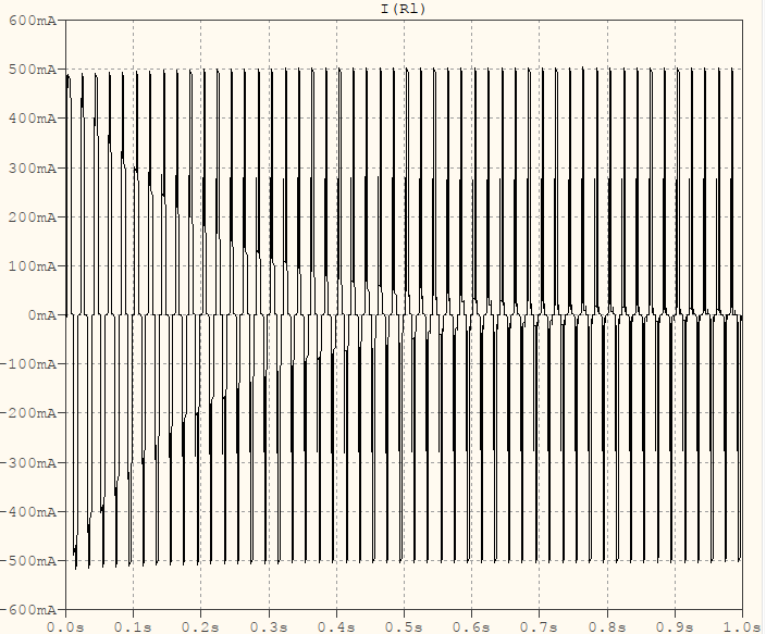
not what's needed

It looks like there's a capacitor discharge problem but, if I increase their values, nothing changes except the time contant -- eventually the response looks like this, only time-stretched/shrinked. There must be something more which I don't know. If you think it will help you, here is how the schematic was transformed: [edit - deleted]


[edit]

After searching a bit more I came across an extremely rare case of a paper that could be acessed on IEEE: A 2 kW, Single-Phase, 7-Level Flying Capacitor Multilevel Inverter with an Active Energy Buffer. It's a 7-level but, on page 3, it shows the missing information about how the command pulses should be. Reading through it it also explains that these inverters are not driven at the grid frequency -- they're modulated by a carrier (symmetrical triangle) which, due to the flying capacitor topology, makes it appear that the output modulating frequency appears N-1 times larger, while also having considerably less ripple after filtering (the LC filter, itself, can have smaller values).

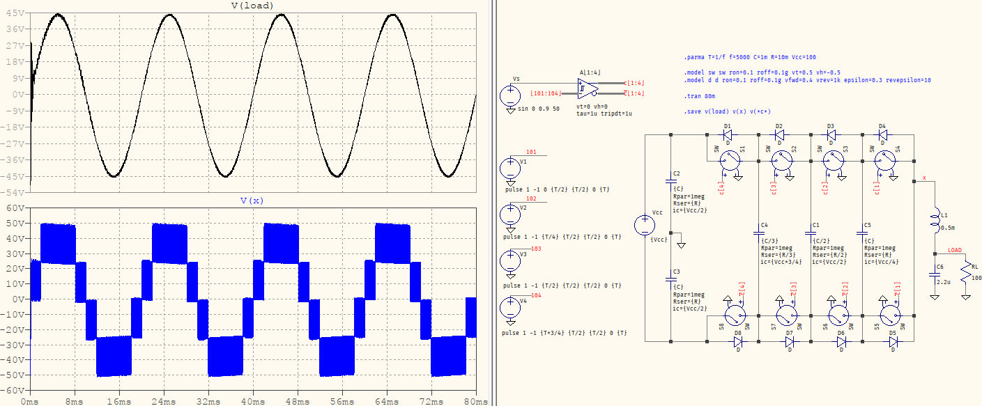
So that link on YouTube above is bogus and here is how the schematic looks like now:

5-level flying capacitor

Since it looks like what you're interested most is to see the behaviour of the circuit, I've changed the transistors for VCSW+D, for faster simulation. And below is the source for the schematic:

Version 4
SHEET 1 5660 3772
WIRE 4144 -80 3936 -80
WIRE 4288 -80 4208 -80
WIRE 4144 -48 4096 -48
WIRE 4288 -48 4208 -48
WIRE 4432 80 4352 80
WIRE 4544 80 4432 80
WIRE 4576 80 4544 80
WIRE 4704 80 4640 80
WIRE 4736 80 4704 80
WIRE 4864 80 4800 80
WIRE 4896 80 4864 80
WIRE 5024 80 4960 80
WIRE 5056 80 5024 80
WIRE 5184 80 5120 80
WIRE 4000 144 3936 144
WIRE 4048 144 4000 144
WIRE 4544 160 4544 80
WIRE 4576 160 4544 160
WIRE 4704 160 4704 80
WIRE 4704 160 4656 160
WIRE 4736 160 4704 160
WIRE 4864 160 4864 80
WIRE 4864 160 4816 160
WIRE 4896 160 4864 160
WIRE 5024 160 5024 80
WIRE 5024 160 4976 160
WIRE 5056 160 5024 160
WIRE 5184 160 5184 80
WIRE 5184 160 5136 160
WIRE 4432 192 4432 80
WIRE 4592 224 4592 208
WIRE 4752 224 4752 208
WIRE 4912 224 4912 208
WIRE 5072 224 5072 208
WIRE 5184 224 5184 160
WIRE 5216 224 5184 224
WIRE 5248 224 5216 224
WIRE 4000 288 3936 288
WIRE 4048 288 4000 288
WIRE 5248 304 5248 224
WIRE 4352 320 4352 80
WIRE 4704 352 4704 160
WIRE 4864 352 4864 160
WIRE 5024 352 5024 160
WIRE 4432 384 4432 256
WIRE 4464 384 4432 384
WIRE 4464 416 4464 384
WIRE 4000 432 3936 432
WIRE 5248 448 5248 384
WIRE 5312 448 5248 448
WIRE 5344 448 5312 448
WIRE 5344 464 5344 448
WIRE 5248 480 5248 448
WIRE 4432 496 4432 384
WIRE 4000 576 3936 576
WIRE 5248 576 5248 544
WIRE 5344 576 5344 544
WIRE 4656 592 4656 576
WIRE 4816 592 4816 576
WIRE 4976 592 4976 576
WIRE 5136 592 5136 576
WIRE 4592 640 4544 640
WIRE 4704 640 4704 416
WIRE 4704 640 4672 640
WIRE 4752 640 4704 640
WIRE 4864 640 4864 416
WIRE 4864 640 4832 640
WIRE 4912 640 4864 640
WIRE 5024 640 5024 416
WIRE 5024 640 4992 640
WIRE 5072 640 5024 640
WIRE 5184 640 5184 224
WIRE 5184 640 5152 640
WIRE 4352 720 4352 400
WIRE 4432 720 4432 560
WIRE 4432 720 4352 720
WIRE 4544 720 4544 640
WIRE 4544 720 4432 720
WIRE 4608 720 4544 720
WIRE 4704 720 4704 640
WIRE 4704 720 4672 720
WIRE 4768 720 4704 720
WIRE 4864 720 4864 640
WIRE 4864 720 4832 720
WIRE 4928 720 4864 720
WIRE 5024 720 5024 640
WIRE 5024 720 4992 720
WIRE 5088 720 5024 720
WIRE 5184 720 5184 640
WIRE 5184 720 5152 720
FLAG 5312 448 LOAD
FLAG 4464 416 0
FLAG 3936 224 0
FLAG 4000 144 101
FLAG 4288 -80 c[1:4]
FLAG 4288 -48 _c[1:4]
FLAG 3936 512 0
FLAG 4000 432 103
FLAG 3936 368 0
FLAG 4000 288 102
FLAG 3936 656 0
FLAG 4000 576 104
FLAG 4096 -48 [101:104]
FLAG 4640 208 0
FLAG 4592 224 c[4]
FLAG 4800 208 0
FLAG 4752 224 c[3]
FLAG 4960 208 0
FLAG 4912 224 c[2]
FLAG 5120 208 0
FLAG 5072 224 c[1]
FLAG 5088 592 0
FLAG 5136 576 _c[1]
FLAG 4928 592 0
FLAG 4976 576 _c[2]
FLAG 4768 592 0
FLAG 4816 576 _c[3]
FLAG 4608 592 0
FLAG 4656 576 _c[4]
FLAG 3936 0 0
FLAG 5248 576 0
FLAG 5344 576 0
FLAG 5216 224 x
SYMBOL res 5328 448 R0
SYMATTR InstName RL
SYMATTR Value 100
SYMBOL voltage 4352 304 R0
WINDOW 123 0 0 Left 0
WINDOW 39 0 0 Left 0
WINDOW 3 17 100 Left 2
SYMATTR InstName Vcc
SYMATTR Value {Vcc}
SYMBOL voltage 3936 128 R0
WINDOW 0 29 34 Left 2
WINDOW 3 -16 121 Left 2
SYMATTR InstName V1
SYMATTR Value pulse 1 -1 0 {T/2} {T/2} 0 {T}
SYMBOL voltage 3936 272 R0
WINDOW 0 29 34 Left 2
WINDOW 3 -21 123 Left 2
SYMATTR InstName V2
SYMATTR Value pulse 1 -1 {T/4} {T/2} {T/2} 0 {T}
SYMBOL Digital\\diffschmitt 4144 -128 R0
WINDOW 3 -3 121 Left 2
WINDOW 123 -3 143 Left 2
SYMATTR Value vt=0 vh=0
SYMATTR Value2 tau=1u tripdt=1u
SYMATTR InstName A[1:4]
SYMBOL sw 4672 160 M270
SYMATTR InstName S1
SYMBOL diode 4640 96 M270
WINDOW 0 32 32 VTop 2
WINDOW 3 0 32 VBottom 2
SYMATTR InstName D1
SYMBOL sw 4832 160 M270
SYMATTR InstName S2
SYMBOL diode 4800 96 M270
WINDOW 0 32 32 VTop 2
WINDOW 3 0 32 VBottom 2
SYMATTR InstName D2
SYMBOL sw 4992 160 M270
SYMATTR InstName S3
SYMBOL diode 4960 96 M270
WINDOW 0 32 32 VTop 2
WINDOW 3 0 32 VBottom 2
SYMATTR InstName D3
SYMBOL sw 5152 160 M270
SYMATTR InstName S4
SYMBOL diode 5120 96 M270
WINDOW 0 32 32 VTop 2
WINDOW 3 0 32 VBottom 2
SYMATTR InstName D4
SYMBOL sw 5056 640 M90
SYMATTR InstName S5
SYMBOL diode 5088 704 M90
WINDOW 0 0 32 VBottom 2
WINDOW 3 32 32 VTop 2
SYMATTR InstName D5
SYMBOL sw 4896 640 M90
SYMATTR InstName S6
SYMBOL diode 4928 704 M90
WINDOW 0 0 32 VBottom 2
WINDOW 3 32 32 VTop 2
SYMATTR InstName D6
SYMBOL sw 4736 640 M90
SYMATTR InstName S7
SYMBOL diode 4768 704 M90
WINDOW 0 0 32 VBottom 2
WINDOW 3 32 32 VTop 2
SYMATTR InstName D7
SYMBOL sw 4576 640 M90
SYMATTR InstName S8
SYMBOL diode 4608 704 M90
WINDOW 0 0 32 VBottom 2
WINDOW 3 32 32 VTop 2
SYMATTR InstName D8
SYMBOL cap 4688 352 R0
WINDOW 39 24 78 Left 2
WINDOW 123 24 100 Left 2
WINDOW 40 22 122 Left 2
SYMATTR SpiceLine Rpar=1meg
SYMATTR Value2 Rser={R/3}
SYMATTR InstName C4
SYMATTR Value {C/3}
SYMATTR SpiceLine2 ic={Vcc*3/4}
SYMBOL voltage 3936 -96 R0
WINDOW 0 9 2 Left 2
SYMATTR InstName Vs
SYMATTR Value sin 0 0.9 50
SYMBOL voltage 3936 560 R0
WINDOW 0 29 34 Left 2
WINDOW 3 -26 134 Left 2
SYMATTR InstName V4
SYMATTR Value pulse 1 -1 {T*3/4} {T/2} {T/2} 0 {T}
SYMBOL voltage 3936 416 R0
WINDOW 0 29 34 Left 2
WINDOW 3 -21 130 Left 2
SYMATTR InstName V3
SYMATTR Value pulse 1 -1 {T/2} {T/2} {T/2} 0 {T}
SYMBOL ind 5232 288 R0
SYMATTR InstName L1
SYMATTR Value 0.5m
SYMBOL cap 5232 480 R0
SYMATTR InstName C6
SYMATTR Value 2.2u
SYMBOL cap 4848 352 R0
WINDOW 39 24 78 Left 2
WINDOW 123 24 100 Left 2
WINDOW 40 22 122 Left 2
SYMATTR SpiceLine Rpar=1meg
SYMATTR Value2 Rser={R/2}
SYMATTR InstName C1
SYMATTR Value {C/2}
SYMATTR SpiceLine2 ic={Vcc/2}
SYMBOL cap 5008 352 R0
WINDOW 39 24 78 Left 2
WINDOW 123 24 100 Left 2
WINDOW 40 22 122 Left 2
SYMATTR SpiceLine Rpar=1meg
SYMATTR Value2 Rser={R}
SYMATTR InstName C5
SYMATTR Value {C}
SYMATTR SpiceLine2 ic={Vcc/4}
SYMBOL cap 4416 192 R0
WINDOW 39 24 78 Left 2
WINDOW 123 24 100 Left 2
WINDOW 40 22 122 Left 2
SYMATTR SpiceLine Rpar=1meg
SYMATTR Value2 Rser={R}
SYMATTR InstName C2
SYMATTR Value {C}
SYMATTR SpiceLine2 ic={Vcc/2}
SYMBOL cap 4416 496 R0
WINDOW 39 24 78 Left 2
WINDOW 123 24 100 Left 2
WINDOW 40 22 122 Left 2
SYMATTR SpiceLine Rpar=1meg
SYMATTR Value2 Rser={R}
SYMATTR InstName C3
SYMATTR Value {C}
SYMATTR SpiceLine2 ic={Vcc/2}
TEXT 4472 -40 Left 2 !.tran 80m
TEXT 4472 -160 Left 2 !.parma T=1/f f=5000 C=1m R=10m Vcc=100
TEXT 4472 8 Left 2 !.save v(load) v(x)
TEXT 4472 -112 Left 2 !.model sw sw ron=0.1 roff=0.1g vt=0.5 vh=-0.5\n.model d d ron=0.1 roff=0.1g vfwd=0.4 vrev=1k epsilon=0.3 revepsilon=10
\$\endgroup\$
3
  • 1
    \$\begingroup\$ I've looked again at the video and the creator is not using the load properly: the voltage sensor is used in series with the load, meaning there is no output current. Strangely, doing the same in LTspice still doesn't show the same result, not even if I tweak the initial conditions for the capacitors. So I'm still reluctant as to what concerns the control pulses. \$\endgroup\$ Commented Nov 18, 2022 at 8:20
  • 1
    \$\begingroup\$ I've updated the answer, it should provide the correct output now. \$\endgroup\$ Commented Nov 19, 2022 at 21:16
  • \$\begingroup\$ It will be very useful. I have used that same video to do the simulation in Simulink and then I realized the mistake that the creator makes when using the measuring instrument. I was thinking about it and I could not find a correct way of switching, using that topology. The paper you mention was very enlightening. \$\endgroup\$
    – loromalo
    Commented Nov 27, 2022 at 17:26
1
\$\begingroup\$

The model has a lot of nodes that are hard to determine the voltage for, this is because most of your sources are floating above ground. The whole circuit is unstable. They need to be fixed. Either redesign the circuit, or you could try fixing some of the nodes with a large resistor (like 1MegΩ or 100MegΩ) to ground.

The current sources also just waste time, you could replace one of these with a voltage source and it would be the same thing without all the computation which could also be throwing off the solver:

enter image description here

\$\endgroup\$
3
  • \$\begingroup\$ The thing about the floating nodes is not necessarily true. All the Sx nodes have a DC path to ground via the FET body diodes' GMIN and the load. Also, the G-source doesn't add too much to the circuit matrix, but you are technically correct. Actually, it would be the most computationally efficient if the voltage source was removed and the G-source was turned into an independent current source (I-source). \$\endgroup\$
    – Ste Kulov
    Commented Nov 18, 2022 at 6:40
  • \$\begingroup\$ The diodes are nonlinear and hard to solve for, they are not a good way to find a DC operating point \$\endgroup\$
    – Voltage Spike
    Commented Nov 18, 2022 at 7:14
  • \$\begingroup\$ GMIN region is linear and not hard to solve for. Anyway, your statements are good tips for broad general SPICE use, but I don't think they are well-matched for the specific circuit/problem at hand. Just my opinion. I'll shut-up now. \$\endgroup\$
    – Ste Kulov
    Commented Nov 18, 2022 at 15:39

Your Answer

By clicking “Post Your Answer”, you agree to our terms of service and acknowledge you have read our privacy policy.

Not the answer you're looking for? Browse other questions tagged or ask your own question.