0
\$\begingroup\$

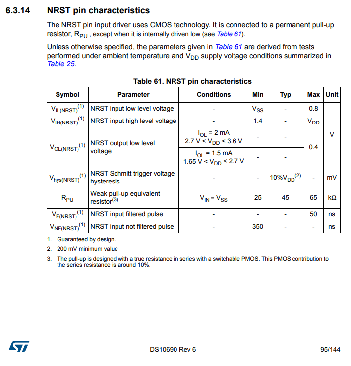
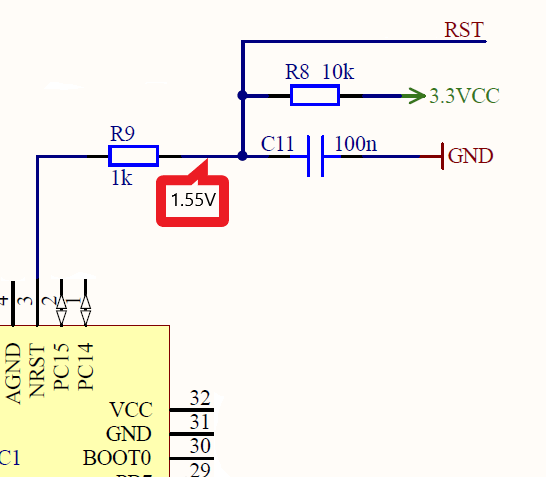
I need help by understanding the problem with an existing MCU circuit concerning the Reset PIN (STM32 Cortex M0+: STM32L071K8): It seems something in the circuit is wrong, since it works only when I am connecting an external Debugger which forces the RST signal to about 3,3V.

If I disconnect the debugger, the MCU is not running properly (I have some LEDs on the PCB to prove this). I measured the value on the RST-Pin between resistors R8 and R9 and without the debugger the value is just about 1.55V. Thus, it seems for me, that the pull up resistor circuitry is obviously not working as intended.But I cannot idetify the concrete bug. The design came not from myself and as a SW developer, I just have limited electronics skills.

Can someone please explain me, what's wrong here with this reset circuit and why does this voltage dropped down to about 1.55V?

enter image description here enter image description here enter image description here

\$\endgroup\$
5
  • \$\begingroup\$ What does the datasheet of the MCU (which MCU?) say about its NRST pin? Mabye that's simply pulled down internally with 9-10 kΩ. \$\endgroup\$ Commented Jun 22, 2019 at 16:04
  • \$\begingroup\$ The MCU is a STM32 Cortex M0+: STM32L071K8 -> st.com/resource/en/datasheet/stm32l071v8.pdf \$\endgroup\$ Commented Jun 22, 2019 at 16:09
  • \$\begingroup\$ Things you can try... Measure the voltage on the other side of R8 to confirm you do have 3.3V. If you have access to a soldering iron, disconnect one of the sides of R8, measure its resistance to confirm it's a 10kΩ part; disconnect one side of C11 and check if the voltage goes up (the capacitor may be defective). Measure the voltage on the other side of R9 and calculate the current in or out the NRST pin based on the voltage drop. Search your schematic to make sure there's nothing else connected to the RST net besides the debugger connector. \$\endgroup\$
    – joribama
    Commented Jun 22, 2019 at 16:31
  • \$\begingroup\$ The part has an internal pullup, so either the "RST" that exits your schematic to the right has something pulling it down, the processor is broken, there's a resistor installed where C11 should be, or there's a board fault. Is this the only board that's got troubles? Has your hardware person looked at it yet? \$\endgroup\$
    – TimWescott
    Commented Jun 22, 2019 at 16:32
  • \$\begingroup\$ Many thanks for your fast responses! I just found the reason: I always only removed the mini-USB cable from the debugger (ST-Link V2), but had not removed the plug with the SWD&RST signals. Therefore the RST-pin was still connected to the unpowered debugger and got pulled-down by this... I am sorry, I thought the problem would lay inside the layout... \$\endgroup\$ Commented Jun 22, 2019 at 16:48

2 Answers 2

2
\$\begingroup\$

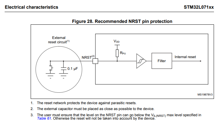
While problem was elsewhere, the reset circuit is still against STM32 suggested circuit. It does not need the pull-up at all, and the 1k in series should not be there.

\$\endgroup\$
2
\$\begingroup\$

Many thanks for your fast responses! I just found the reason: I always only removed the mini-USB cable from the debugger (ST-Link V2), but had not removed the plug with the SWD&RST signals. Therefore the RST-pin was still connected to the unpowered debugger and got pulled-down by this... I am sorry, I thought the problem would lay inside the layout.

\$\endgroup\$
1

Your Answer

By clicking “Post Your Answer”, you agree to our terms of service and acknowledge you have read our privacy policy.

Not the answer you're looking for? Browse other questions tagged or ask your own question.