1
\$\begingroup\$

Goal:

I am attempting to only turn on the fan when the THERM signal of the temp IC (IC2 in schematic) goes LOW. The IC works in that it triggers an active low on THERM when a temp threshold is crossed (40degC in our case)

Issue:

  1. The fan is on at the beginning even before the active low is triggered (5V still passing through emitter to collector).

  2. The active low does little to the base voltage (I measured over 4V at the base even though I verified almost zero at THERM) I chose a PNP BJT because I thought ON would be triggered from a low signal and OFF when high..but this doesn't seem to be the case. Does it have something to do with my Vb < Ve at the beginning? (3.3 at base through pull up resistor vs 5 at emitter?)

Could someone possibly recommend a transistor that might work in this application? Thanks so much!

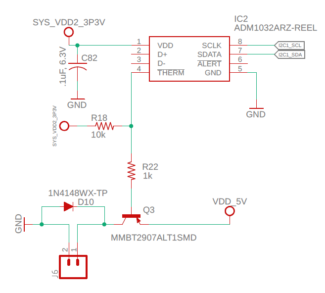
enter image description here

\$\endgroup\$
0

3 Answers 3

0
\$\begingroup\$

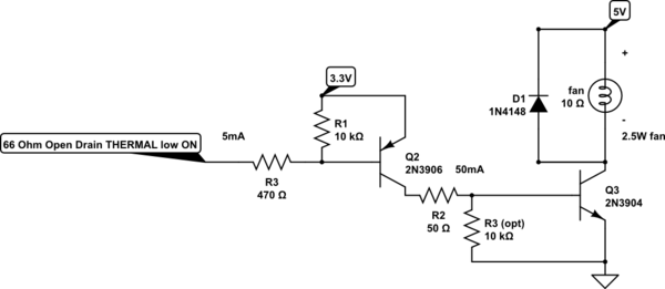
1) 3.3V 10k pullup will pull down PNP base and turn on fan

R18 must use same 5V but not connected to THERM since IC uses 3.3V

2) PNP needs base drive resistor near 220 to 300 Ohms to drive 0.5A fan.

spec p15 "As mentioned above, the THERM signal is open drain and requires a pullup to VDD. The THERM signal must always be pulled up to the same power supply as the ADM1032, unlike the SMBus signals (SDA, SCL and ALERT) that can be pulled to a different power rail. The only time the THERM pin can be pulled to a different supply rail (other than VDD) is if the other supply is powered up simultaneous with, or after the ADM1032 main VDD. This is to protect the internal circuitry of the ADM1032. If the THERM pullup supply rail were to rise before VDD, the POR circuitry may not operate correctly.

The base of the PNP if at 4V should turn on the Fan at 5V. That means the Vbe = 1V which is normally max.

A better solution to avoid the POR issue above and use 2 stages with a low side NPN switch.

schematic

simulate this circuit – Schematic created using CircuitLab

This will also work for higher fan voltages.

I am assuming you are using a small muffin fan.

\$\endgroup\$
5
  • \$\begingroup\$ Sunnyskyguy I am a little confused however, you have the pnp stage before the npn. So when THERM goes low 3.3 will pass through to the base of the npn (q3), wont this voltage still not turn on q3 since since still less than V at q3s collector (5V)? \$\endgroup\$
    – wgthompson
    Commented Oct 11, 2019 at 22:20
  • \$\begingroup\$ By the way I am using OD4010-05HB55-FAN, about .19A draw \$\endgroup\$
    – wgthompson
    Commented Oct 11, 2019 at 22:22
  • \$\begingroup\$ Also quick question, if I were to want to use a more potent fan (lets say 12v) would this approach still work? \$\endgroup\$
    – wgthompson
    Commented Oct 11, 2019 at 22:27
  • \$\begingroup\$ added current limit base R. higher V+ ok \$\endgroup\$
    – D.A.S.
    Commented Oct 12, 2019 at 5:18
  • \$\begingroup\$ Even a 100Vdc fan can be driven this way as long as the base driver gives at least 5~10% of the load current. \$\endgroup\$
    – D.A.S.
    Commented Oct 12, 2019 at 13:04
1
\$\begingroup\$

To put the PNP transistor in cutoff you need to bring THERM up to the transistor's emitter voltage, 5V, instead of just 3.3V. You could connect R18 to 5V but that might damage the temperature sensor.

The general solution to this problem is to add an NPN transistor that will drive the base of Q3. The NPN transistor can be switched with the 3.3V sensor voltage but will easily control the PNP base. Of course, the sense of the alarm signal is now inverted so you probably need to change the setup of the THERM output accordingly.

\$\endgroup\$
2
  • \$\begingroup\$ Would the simplest solution be to power the temp ic at 5 and just pull R18 to 5? \$\endgroup\$
    – wgthompson
    Commented Oct 11, 2019 at 22:23
  • \$\begingroup\$ Sunnyskyguy EE75 below recommends pnp to drive npn, wouldn't this alleviate the need to invert THERM? \$\endgroup\$
    – wgthompson
    Commented Oct 11, 2019 at 22:25
0
\$\begingroup\$

As Elliot Anderson suggested an NPN would be better. The NPN has a rougly 0.7V drop across it, which if the fan has a tach or PWM speed output, running the base of the fan at 0.7V might not be good for the PWM output or tach output. The NPN will also burn up power in it if the fan has a lot of current.

(0.7V x fan current) = Watts dissipated in NPN

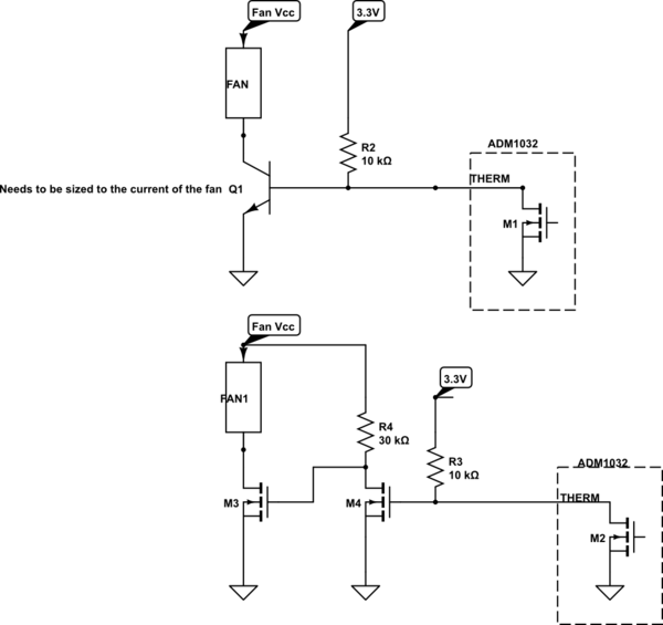
Here are some basic ideas for circuits that could be used in a design like this

A better more lossless way uses two nmos transistors. M4 inverts the logic and pulls the gate of M3 to the fan Vcc.

If you wanted to invert the logic, remove M4 and run M3's gate directly from \Therm and the 10k pullup

schematic

simulate this circuit – Schematic created using CircuitLab

\$\endgroup\$
8
  • \$\begingroup\$ Unfortunately R2 is too big to drive with insufficient base current. If a 5V fan is 2.5W or 0.5A or ~ 10 Ohms, R2 needs to be around 220 Ohms in NPN cct \$\endgroup\$
    – D.A.S.
    Commented Oct 11, 2019 at 17:57
  • \$\begingroup\$ I assume that the OP knows how to swap a resistor, I don't know what the fan current is \$\endgroup\$
    – Voltage Spike
    Commented Oct 11, 2019 at 18:01
  • \$\begingroup\$ You cannot drive any fans with 10k = 260 uA base current \$\endgroup\$
    – D.A.S.
    Commented Oct 11, 2019 at 18:07
  • \$\begingroup\$ I can with an ideal NPN, which is what I have listed in the schematic. \$\endgroup\$
    – Voltage Spike
    Commented Oct 11, 2019 at 18:10
  • \$\begingroup\$ ideal wont work. Current Gain of 30 may be practical not 1000 \$\endgroup\$
    – D.A.S.
    Commented Oct 11, 2019 at 18:20

Your Answer

By clicking “Post Your Answer”, you agree to our terms of service and acknowledge you have read our privacy policy.

Not the answer you're looking for? Browse other questions tagged or ask your own question.