4
\$\begingroup\$

I am new to electronics, and I'm reading a book on embedded systems and bumped into an "Open Collector". I know that a transistor has a base, which acts like a switch for the current to flow from collector to emitter, but what does open collector mean?

What is it (in simple terms!), what does it do, and where to use it?

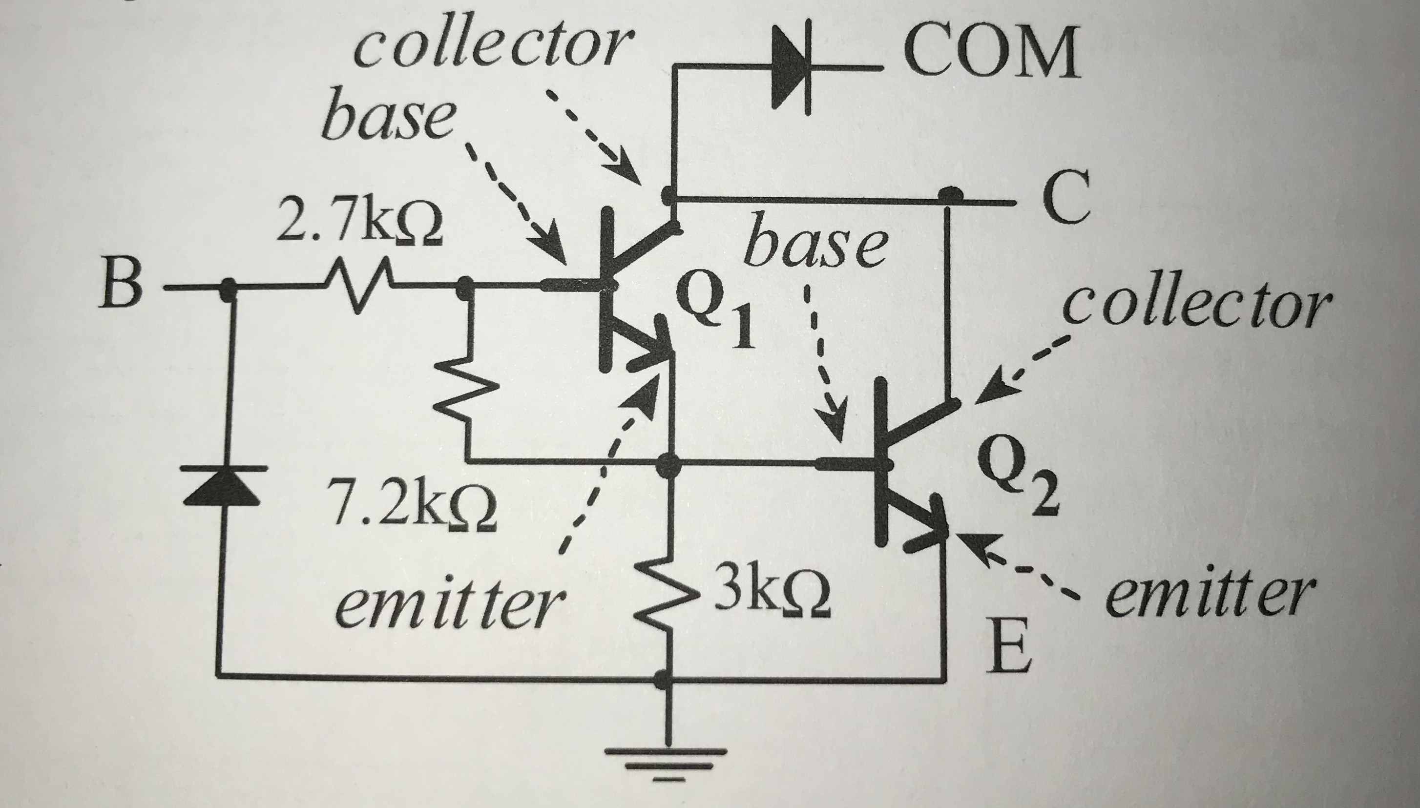
The picture below shows the one I got stuck on. For the record, don't ask me about what COM signal means.. The picture is something called a darlington transistor. (From the book "Introduction to ARM cortex M microcontrollers")

Darlington transistor

\$\endgroup\$
6
  • 3
    \$\begingroup\$ this has got to be a duplicate, right? \$\endgroup\$
    – vicatcu
    Commented Dec 26, 2019 at 20:06
  • 1
    \$\begingroup\$ @vicatcu Probably \$\endgroup\$
    – DKNguyen
    Commented Dec 26, 2019 at 20:07
  • 1
    \$\begingroup\$ think of a SPST switch ... one terminal is connected to ground ... the other terminal is connected to the output ... closing the switch connects the output to ground ... opening the switch disconnects the output from ground and allows the output to "float" \$\endgroup\$
    – jsotola
    Commented Dec 26, 2019 at 20:28
  • \$\begingroup\$ The collector is not connected internally to Vcc but allows the collector to be connected to an arbitrary supply voltage through a load. The fly-back diode may also be connected across the load if this is inductive. \$\endgroup\$
    – Chu
    Commented Dec 26, 2019 at 20:46
  • \$\begingroup\$ tell what you think COM means \$\endgroup\$
    – D.A.S.
    Commented Dec 26, 2019 at 21:20

4 Answers 4

6
\$\begingroup\$

At first glance, the circuit you show looks a lot like a single channel of a ULN2003A 7-channel Darlington driver. Each ULN2003A channel is a Darlington driver: a circuit where one transistor directly drives another transistor to get a combined current gain far higher than the gain of either transistor.

The COM diode in each ULN2003A channel is useful if any of the open-drain drivers are switching an inductive load, like a relay or a solenoid. The diodes can clamp the back emf of the inductive loads, though all inductive loads must use a common supply higher than for loads on the non-inductive channels. The COM diodes save on external diodes when the ULN2003A is driving 7 inductive loads from the same supply. It's an IC for driving things like solenoids in printers decades ago and the ULN2003A is far past its prime, with high switching losses compared to modern FET switch ICs.

With that aside, let's answer your question...

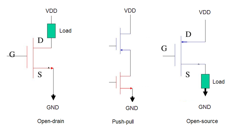
Open-collector is a type of switched load driver circuit, along with open-emitter and push-pull. The terms 'open-collector' and 'open-emitter' are used when the switching component is a bipolar junction transistor (BJT), as collector and emitter are BJT terminals. If the switches are FETs, 'open-drain' and 'open-source' are used.

In a switched driver, the output transistors are either switched hard on (saturated) or switched hard off, never partially conducting. They act like simple on/off switches. In reality, there's more going on than that but the simple view lets us grasp the basics.

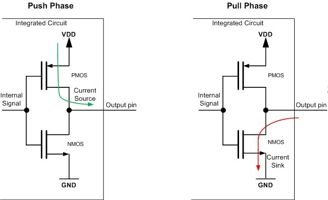
The comprehensive switching driver circuit to use is a push-pull output. This consists of two switching transistors - FETs in the example below.
enter image description here

When one FET is on, the other one is off, so the the circuit has two driving states:

(1) When the upper FET is ON, the lower FET is OFF and the circuit is driving a 'high' voltage that can source (supply) current to its output.

(2) When the upper FET is OFF, the lower FET is ON and the circuit is driving a 'low' voltage that can sink (take) current from its output.

Ideally, 'high' voltage would be VDD and 'low' voltage would be GND, but the FETs have losses and can't quite reach those voltages.

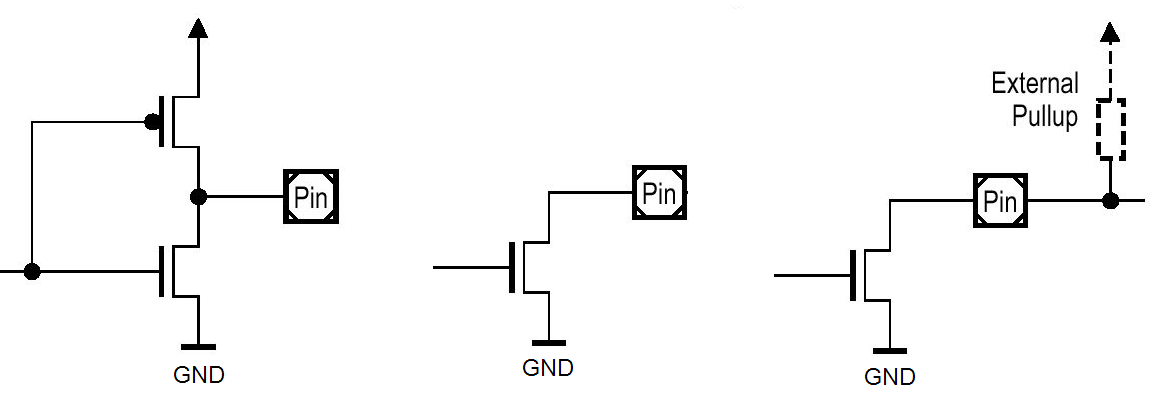
A open-collector driver is a BJT circuit containing the lower transistor that sinks current but no upper transistor to source any current. Again, when FETs are used it's called an open-drain driver.

As shown in the diagram below, the push-pull FET circuit (left) has had the upper FET removed to make an open-drain driver (middle). When the lower FET (middle) is ON, current can flow through the transistor to GND. When the lower FET is OFF, there is no current flow and the output is said to be at 'high impedance', or 'floating' if not connected to anything.

An external circuit must supply the current to flow through the lower FET. This could be a pull-up resistor (right).
enter image description here

In a similar way, the open-source driver FET circuit has an upper transistor and no lower transistor. It can supply current to the output or be at high impedance.

All three driver circuits are illustrated in these FET circuits.
enter image description here

There is plenty more you can read up yourself on the internet on these circuits. But this should give you the basics to find, understand and learn it.

\$\endgroup\$
3
\$\begingroup\$

The schematic you show is a partial schematic of a ULN2003A or similar Darlington driver array. COM is a common rail (typically) used for the catch (flyback) diodes when inductive loads are being switched.

The two collectors connected together do go to the diode so they're not completely open, but that diode does not normally conduct- only briefly when an inductive load is switched off, so ignore it for the purposes of this discussion.

A Darlington pair is sort of a compound transistor with very high current gain. The usual textbook depiction is two transistors connected thusly:

schematic

simulate this circuit – Schematic created using CircuitLab

The practical circuit in the ULN2003A includes resistors to make sure the gain is not excessively high and a parasitic diode is also shown.

The collectors in both the Darlington pair and the simple BJT are "open". If you drive the inputs with a (say) 0V/5V you won't see much voltage at the collector, they need a load from the collector to some positive rail (such as a pull-up resistor) to get substantial current to flow.

The open-collector (rather than having a resistor or some active circuit as a pull-up) allows to to use a higher voltage than the logic supply, for example, if the ratings allow. You can use an open-collector output ULN2003A to switch a 24V relay from a 5V or 3.3V logic level (since relays are inductive you'd tie COM to +24).

Many analog comparators have open-collector outputs- that allows outputs to be directly tied together with a single pull up resistor such that the output only goes high if all the transistors are off. That's useful, for example for making a window comparator which detects when a voltage is within a certain range.

\$\endgroup\$
2
\$\begingroup\$

It means the collector pin on the output NPN is open when in the HI state. As in it's not connected to a pull-up transistor and can actively drive the output HI.

That means it can only actively drive the output LO, or disconnect it. That means you have to provide a means to bring the output HI (like a pull-up transistor), or in some cases you don't care if the output is HI as much as you only care if it is conducting current or not(like to drive an LED), in which case you don't worry about a pull-up resistor and just connect the LED to it accordingly.

\$\endgroup\$
1
  • \$\begingroup\$ @TonyM That doesn't change the fact that's what the "open" refers to for open collector means, particularly for the most base form of an open collector circuit which the OP's schematic is not. It's about as strict as what what "common" means in common collector and common emitter amplifiers. The "open" doesn't really refer to "the state of the output when the transistor is off" because then the OP could just as easily ask why is that the namesake and not when transistor is conducting? \$\endgroup\$
    – DKNguyen
    Commented Dec 26, 2019 at 20:18
2
\$\begingroup\$

An open collector means nothing is connected to the collector, the collector is left open.
With nothing connected, I mean from the view of the transistor or circuitery which is in front of this 'output'.
When the transistor is not conducting, the voltage of the output is either floating or driven by external components.
When the transistor is conducting, the output is 'shorted' to the emitter of the transistor. In OP's case, the output is 'shorted' to ground.
You have to 'externally' connect something to this open collector to make it useful, like e.g. a pull-up resistor.

The benefit of an open collector lies it the fact that when the transistor is not conducting, the voltage of the output is either floating or driven by other external components.
In this way, you can connect multiple open collector outputs to each other.

If you connect multiple push-pull driver outputs directly together, you will have a problem when one driver tries to push the output up (to e.g. Vcc) and another driver tries to pull down the output (to e.g. GND).

\$\endgroup\$
0

Your Answer

By clicking “Post Your Answer”, you agree to our terms of service and acknowledge you have read our privacy policy.

Not the answer you're looking for? Browse other questions tagged or ask your own question.