0
\$\begingroup\$

I have a 28V power source and a 24V power source on my device. The 28V source is permanent (internal battery) and the 24V can be disconnected. When 24V is connected, the 28V battery needs to be automatically disconnected by some high-side switch. Disconnecting the low side is not possible.

I tried a solution with a FET but failed as 24V is below 28V... How can I design such a switch?

\$\endgroup\$
11
  • \$\begingroup\$ Consider powering a relay with a changeover (SPDT) switch, from the 24V supply. Nice and simple. \$\endgroup\$
    – user16324
    Commented May 20, 2020 at 19:37
  • \$\begingroup\$ Relay is not possible, it needs to be all electronics, no mechanics. The circuit needs to widthstand 200 G. \$\endgroup\$
    – Reto
    Commented May 20, 2020 at 19:39
  • \$\begingroup\$ Somehow I missed that in the question. Seems like an odd requirement. \$\endgroup\$
    – user16324
    Commented May 20, 2020 at 19:40
  • 1
    \$\begingroup\$ So you want to disconnect 28V from the load whenever 24V is present, right? Is the load purely a load? Does it ever act like an energy source and push current back into the battery? Is it even a rechargeable battery? \$\endgroup\$
    – user57037
    Commented May 20, 2020 at 19:47
  • 1
    \$\begingroup\$ @mkeith it is just a load. The battery is being charged by a separate input. \$\endgroup\$
    – Reto
    Commented May 20, 2020 at 19:54

2 Answers 2

2
\$\begingroup\$

I'm not sure what the issue is with using a MOSFET as follows:

schematic

simulate this circuit – Schematic created using CircuitLab

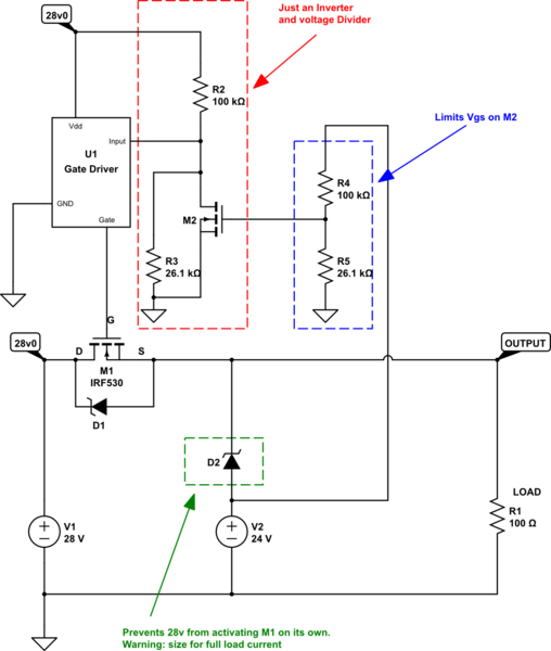
I drew in the body-diode of the MOSFET separately just to remind that it is always there. The only thing you need to do to drive this circuit is ensure that the Gate-Source voltage on the MOSFET is higher than the Vgs threshold voltage of the MOSFET you choose. If that's the problem you are referring to then you need a gate-driver IC with built in boost-voltage/charge-pump. Most of these will be classified under "high-side mosfet driver" - like the MIC5021 datasheet (just the first one that popped up doing a search, not particularly endorsing that one).

The downside to this solution being that you have to conduct into the load through D2, which will cause a small voltage drop and will need to be size to handle the current the load will require.

M2 can be quite small compared to M1 since it is only handling small signals.

\$\endgroup\$
7
  • \$\begingroup\$ You don't show the gate connection. This can work but it is not very helpful without providing all the tricky gate drive details. \$\endgroup\$
    – user57037
    Commented May 20, 2020 at 23:17
  • \$\begingroup\$ The way you connected V2 is not going to work, either. You will see if you try to finish the circuit. \$\endgroup\$
    – user57037
    Commented May 20, 2020 at 23:37
  • \$\begingroup\$ I'm suggesting driving the gate with a charge-pump gate driver IC in the text of the answer, that's why I didn't draw an explicit connection to the gate here. I'm not sure sure what you mean that hooking up V2 like that won't work, happy to change if I missed something though. \$\endgroup\$
    – eceforge
    Commented May 20, 2020 at 23:42
  • \$\begingroup\$ Why don't you show the logic that controls the high-side gate driver. You need to somehow detect when the 24V supply is absent. How would you do that if the output of your high-side switch is directly connected to 24V? \$\endgroup\$
    – user57037
    Commented May 20, 2020 at 23:56
  • 1
    \$\begingroup\$ That's fair, I was mostly trying to make the point that you can indeed do high-side switching of a MOSFET, which the person asking seemed to be confused about. I've update the schematic with more details on the gate-drive circuitry. \$\endgroup\$
    – eceforge
    Commented May 21, 2020 at 1:13
1
\$\begingroup\$

You can try something like this:
enter image description here

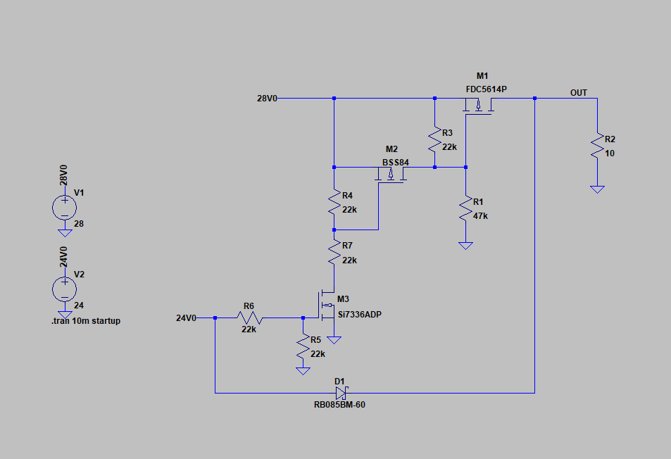
You need to make sure that the pass transistor (M1) can handle the load current. M2 and M3 are low profile FETs (no need for high current capability) used to disable M1 when the 24V source is connected. This will automatically disconnect the 28V source when 24V is present.

Here are the situations you can have (28V is always present as stated in your post):

(1) 24V source is not connected: In this case, M3(NMOS) is OFF because R5 pulls it to ground. R4 keeps M2's(PMOS) source and gate at the same potential, and therefore, stays OFF. The only transistor that is active is M1(PMOS) because R3 and R1 create enough voltage difference between the source and the gate (~10V).

(2) 24V source is connected: In this case, R6 and R5 turn on M3, which as a result turns on M2. R4 and R7 ensure you don't over-voltage M2's VGS. Turning on M2 means that the source and the gate of M1 are at the same potential, and therefore stays OFF, disconnecting the 28V source. D1 provides a path for the 24V source to the output.

The resistor voltage dividers keep the voltages below the max ratings of the transistors. D1 blocks the VOUT node from messing with the 24V node, more specifically, keeps it from creating oscillations when the 24V is not present.

\$\endgroup\$

Your Answer

By clicking “Post Your Answer”, you agree to our terms of service and acknowledge you have read our privacy policy.

Not the answer you're looking for? Browse other questions tagged or ask your own question.