6
\$\begingroup\$

Meanwhile in quarantine I been trying to learn about electronics. I am still not able to understand the voltage drop when it comes to long wires. My goal is to be able to send a 5v signal over a very long wire. I have read a lot about Ohm's law, done a lot of exercises and I am still confused.

Before conducting the real experiment with the long wire I will like to simulate it it. Here is the simulation of what I am doing:

  1. According to google the resistance of the cable I am using is .05 ohms per meter. If the distance is 200 meters that means there will be a resistance of .05 * 200 = 10 ohms.

  2. If I intend to send a 5v signal over a long wire this is my simulation: enter image description here (The long 200 meters wires represent the resistors in the diagram)

  3. According to Ohm's law the current of this circuit will be V=I*R -> 5=I*20 -> I=0.25 amps

  4. Knowing the current I can calculate the voltage drop across each resistor will be V=I*R -> V=0.25*10 -> V=2.5. Therefore the voltages of the circuit will be as:enter image description here(The first part of the circuit has 5 volts. After the long wire there will be 2.5 volts and at the end 0 volts.)

  5. To prove this is correct this is a circuit in real life: enter image description here (The yellow cable comes from the power supply with 5V. Then that is connected to the red cable. The red cable is connected to the 10 Ohms resistor. Then there is a blue cable connected to the other resistor. And finally that is connected to the black cable ground)

  6. If I then use a volt meter I can see the the voltage drop between the red wire and blue wire is 2.5 Volts: enter image description here
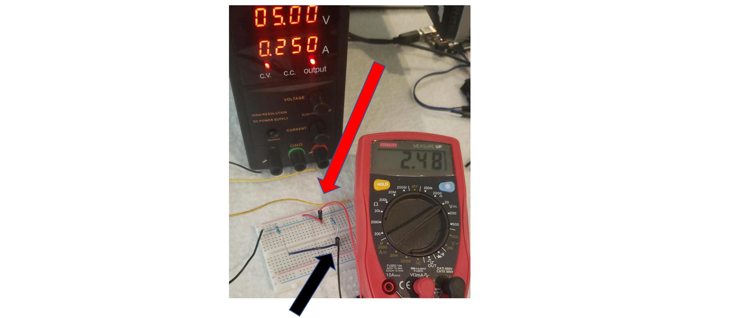
  7. Now here is my question. Why do I still read 5 Volts if I place the proves like this: enter image description here

On the internet everyone says that running 5V signals over long signals is not a good idea. Maybe it is not a good idea if you are planing to send current. I can understand that the current will drop a lot. But the voltage will not correct? On the other end of the 200 meter wire I just want to read a voltage in order to get a signal. What am I doing wrong? Why I cannot send a PWM signal using this approach?

Questions

A. When reading a PWM signal with arduino does arduino read the voltages or the current? I think it reads the Voltage and does not care about current like just like the volt meter? I just want to send a PWM signal over the long wires to trigger an event at the other end.

B. Why people on the internet say there will be a voltage drop when using long cables. I just simulated a very long cable and I am still able to read 5 Volts.

Solution

I know the solution will be to use an optocoupler with a higher voltage because I been researching on the internet. But I still want to understand why is my approach not correct and will probably not work.

Edit

Sorry I broke the circuit. If I place a 10K resistor in order to complete the circuit I still read 5V.

enter image description here

The circuit is complete and I am still reading 5V over the 200meters wire.

\$\endgroup\$
4
  • 2
    \$\begingroup\$ Tip: The earth or ground symbol represents plates of metal buried horizontally in the ground. The symbol should always point downwards to the ground. \$\endgroup\$
    – Transistor
    Commented May 27, 2020 at 22:08
  • \$\begingroup\$ Stupid question: Where is your load in that first diagram? \$\endgroup\$
    – Hot Licks
    Commented May 28, 2020 at 20:27
  • \$\begingroup\$ You do not need a load to have a circuit. I probably draw it wrong because I am learning. If it is a stupid question why does it have 3 likes? Everyone understood it but you @HotLicks. \$\endgroup\$
    – Tono Nam
    Commented May 29, 2020 at 0:34
  • \$\begingroup\$ @TonoNam - Look at the answers below. No load, no voltage drop. \$\endgroup\$
    – Hot Licks
    Commented May 29, 2020 at 1:04

6 Answers 6

5
\$\begingroup\$

A) Arduino analog input reads voltages.

B) People in the internet send current over the wire, so wire resistance causes drop. The case where your circuit has no current flowing has also no drop.

\$\endgroup\$
10
\$\begingroup\$

schematic

simulate this circuit – Schematic created using CircuitLab

Figure 1. Feeding a short-circuit, feeding a reasonable load and feeding an open-circuit.

  • In the first case you have a short-circuit at the load end so the voltage is zero and no useful work is done. The current through the circuit will be \$ I = \frac V R = \frac 5 {20} = 0.25\ \text A \$.
  • In the second case you have a reasonable load of 980 Ω (just chosen to make the maths easy). The current through the circuit is \$ I = \frac V R = \frac 5 {1000} = 5\ \text {mA} \$. The voltage at the load will be 4.9 V and the total drop caused by the loop will be 0.1 V.
  • In the third case the circuit is open. No current is flowing so there is no voltage drop across the 10 Ω resistors. The voltage measured will be 5 V.
\$\endgroup\$
5
\$\begingroup\$

Why do I still read 5 Volts if I place the proves like this

In this picture you've removed the wire connecting the two resistors.

Therefore there is no current flowing through the 1st 10-ohm resistor. So, by Ohm's Law, there is no voltage drop across it, and both of its ends are at +5 V.

And there is no current flowing through the 2nd 10-ohm resistor. So, by Ohm's Law, there is no voltage drop across it and both of its ends are at 0 V.

And the difference between 5 V and 0 v is 5 V.

\$\endgroup\$
11
  • \$\begingroup\$ Thanks for the help! If I complete the circuit and place a 10K resistor I read 5 V still. \$\endgroup\$
    – Tono Nam
    Commented May 27, 2020 at 21:22
  • 1
    \$\begingroup\$ @TonoNam, so calculate the current flowing through each resistor in that scenario and see whether your result makes sense or not. I calculate you should have measured about 4.99 V rather than 5 V. \$\endgroup\$
    – The Photon
    Commented May 27, 2020 at 21:24
  • 1
    \$\begingroup\$ @TonoNam your simulation is flawed. You would not short circuit the remote end when receiving voltage. If you do, you'd have 2.5V on both wires, so you could not measure a voltage difference. However, same 250mA current would still flow. \$\endgroup\$
    – Justme
    Commented May 27, 2020 at 21:30
  • \$\begingroup\$ I see if there is no current flowing the voltage will be 0 volts. But why does my volt meter reads 5V then? I am confused. \$\endgroup\$
    – Tono Nam
    Commented May 27, 2020 at 21:30
  • 1
    \$\begingroup\$ Why do you think serial communications do not work? What approach? People use serial comms over 100s of meters of cable just fine. What baud rate? \$\endgroup\$
    – Justme
    Commented May 27, 2020 at 21:36
4
\$\begingroup\$

When you connect a number of resistors in series to a 5V source, if you determine the voltage drop for each resistor and add those figures up, you’ll always get 5 volts. The individual voltage drops will be proportional to the resistances.

When you add the 10k resistor, the resistances are 10, 10000 and 10 ohm, so no wonder the voltage drop across the biggest resistor is almost the entire 5V. When the 10k isn’t present, the voltmeter itself takes its place. By design, voltmeters have high internal resistances (megaohms or more), thus the reading will be very close to 5V.

The problem with having long wires is that their resistances become comparable to those of your load so it’s as though your load were connected to a 3V source or something like that, which might be too low for the load. And if it has a resistance high enough that it’s still way greater than that of the wires, then the current might be too low to get any use of the load.

Thus it all boils down to what the internal resistance of the Arduino measuring circuit is going to be when the pin is put into analog input mode. The spec says it’s 100MΩ, which will allow you to measure your voltage well, the extra resistance of the wires will however delay the charging of the capacitor that Arduino uses. Not by much though, the spec says the internal resistance of the source should be below 10k, your wires aren’t anywhere close to that.

Finally, long wires suffer from EM interference, which might be a bigger problem than a voltage drop, depending on your environment.

\$\endgroup\$
1
  • \$\begingroup\$ This is an excellent first answer. Answers the question succinctly, brings up relevant side issues, and explains it all. Nice formatting and grammar as well. +1 Welcome to electronics.stackexchange, I look forward to your contributions. \$\endgroup\$ Commented May 28, 2020 at 21:21
0
\$\begingroup\$

Other people already answered the question of why your measurements are what they are, I will attempt to approach the problem from your use case.

  1. Arduino analog inputs don't draw much current, so the voltage drop over long cables should be minimal. At 200 meters I would be more concerned about external interference, which can be minimized by keeping the wires closely together (preferably twisting them), but that's a much longer topic.
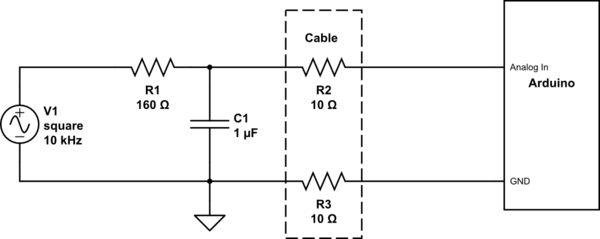
  2. PWM signal is not really an analog voltage signal. It's a square wave, which needs to be filtered to extract the analog voltage you want. A simple RC low pass filter should be enough, like this:

schematic

simulate this circuit – Schematic created using CircuitLab

Presented values are only an example for an 10kHz PWM signal, you can use a calculator like this one to adjust it to your needs. The filter should be placed between the signal source and the cable, so that the cable only has to transmit relatively slow changing voltage. This will reduce interference created by the cable itself.

  1. Unless you need multiple actions triggered by a single cable pair (and the signal source isn't advanced enough for a proper long distance protocol like RS485), using analog voltage is an unnecessary complication. For the simplest on-off control, a simple digital signal should suffice, for example 0-5V signal feeding through a current limiting resistor into a normal digital input of the Arduino (or into an optoisolator if you want protection for the relatively fragile Arduino).
\$\endgroup\$
-1
\$\begingroup\$

You have to have a load to draw current then add subtract the vd from this base. Else it’s into a short circuit not a load. Then there’s impeadence.

\$\endgroup\$
1
  • 1
    \$\begingroup\$ Welcome to EE.SE, Chris. Your answer could do with a few more details if it's to be of any use to the OP (original poster). You can edit to improve. \$\endgroup\$
    – Transistor
    Commented May 29, 2020 at 8:06

Your Answer

By clicking “Post Your Answer”, you agree to our terms of service and acknowledge you have read our privacy policy.

Not the answer you're looking for? Browse other questions tagged or ask your own question.